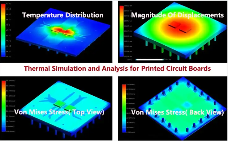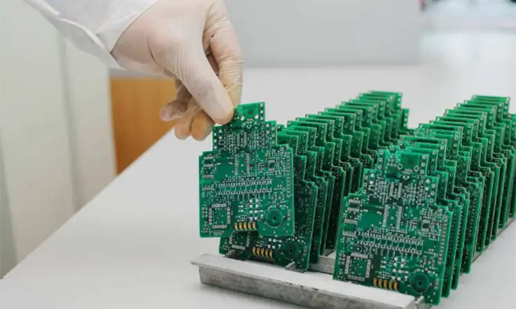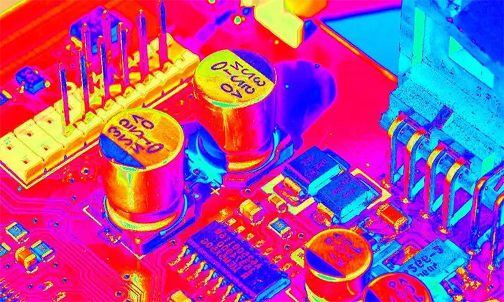
PCB thermal simulation and analysis is a process of modeling and predicting the heat generated by electronic components on a printed circuit board (PCB) and the resulting temperature distribution. As electronic devices become more powerful and compact, the heat generated by the components can create thermal hotspots and cause premature failure or degradation of the system’s performance. Thermal simulation and analysis are important tools to optimize the thermal design of a PCB, improve the reliability, and extend the lifespan of electronic devices.
The main objective of PCB thermal simulation and analysis is to ensure that the temperature of all components on the board stays within the safe operating range. The temperature of electronic components can affect their performance, reliability, and lifespan. Additionally, if the temperature exceeds a certain limit, it can cause irreversible damage or result in catastrophic failures.
PCB thermal simulation and analysis can help identify the thermal hotspots, inefficient heat dissipation mechanisms, and potential failure modes. This information can be used to optimize the thermal design of the PCB, such as placement of components, selection of materials, and configuration of heat sinks and fans. Furthermore, it can help reduce the design and prototyping costs by identifying and correcting thermal issues before physical testing of PCBs.
There are various simulation and analysis tools available to simulate and analyze the thermal behavior of PCBs, including finite element analysis (FEA) and computational fluid dynamics (CFD). These tools allow designers to predict the temperature distribution and heat flow in the PCB and investigate the effect of different design parameters on the thermal performance.
Terminology Related to PCB Thermal Simulation and Analysis
Some of the basic concepts and terminology related to PCB thermal simulation and analysis include:
● Thermal conductivity: A measure of a material’s ability to conduct heat. It is usually denoted by the symbol ‘k’ and measured in units of watts per meter-kelvin (W/mK).
● Thermal resistance: The resistance offered by a material to the flow of heat. It is usually denoted by the symbol ‘R’ and measured in units of kelvin per watt (K/W).
● Heat flow: The transfer of thermal energy from one point to another due to a temperature gradient. It can occur through conduction, convection, and radiation.
● Heat sink: A device that is used to dissipate heat away from electronic components by increasing the surface area exposed to the surrounding air.
● Thermal vias: Small holes drilled in PCBs that are filled with metal to allow for efficient transfer of heat between different layers of the board.
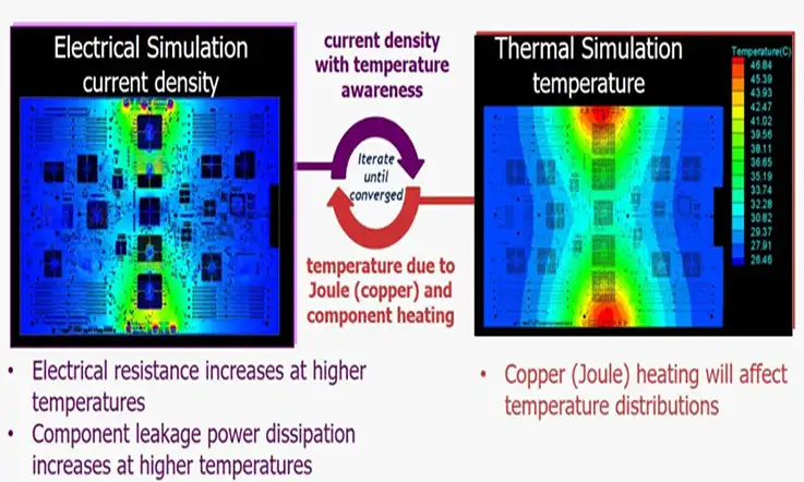
● Joule heating: The process of heat generation due to the flow of electric current through a resistor or conductor.
● Thermal runaway: A condition where the temperature of a component continues to rise due to a positive feedback loop, leading to failure or damage.
● Finite element analysis (FEA): A numerical analysis technique used to model and simulate complex physical systems, including thermal behavior in PCBs.
● Computational fluid dynamics (CFD): A method used to simulate the flow of fluids and heat transfer in complex geometries, including the airflow and heat transfer in PCBs.
● Thermal modeling: The process of creating a mathematical representation of the thermal behavior of a PCB, which can be used for analysis and simulation.
What Is PCB Thermal Simulation ?
Thermal simulation, also referred to as thermal modeling, is an essential tool in conducting successful thermal failure analyses. It aids designers in comprehensively understanding the thermal issues associated with circuit design, as well as identifying suitable strategies for PCB design and cooling.
When equipped with adequate modeling tools, PCB designers can determine the optimal board layout and component arrangement to achieve maximum efficiency. Thermal modeling enables designers to effectively analyze elements such as heat flow patterns, heat sink design, and cooling solutions for active devices.
By utilizing thermal simulation, designers can accurately predict the thermal impact of different design configurations before moving to the physical prototyping stage, reducing the time and costs associated with redesigns. Furthermore, it enables designers to explore a range of design options, compare the thermal performance of each, and select the most effective design for their specific application.
Overall, thermal simulation is a valuable tool in PCB design, enabling designers to more effectively address thermal issues and optimize the performance of their circuits, resulting in more effective overall products.
Why Is It Necessary to Do Thermal Simulation on PCBs ?
Thermal simulation of printed circuit boards (PCBs) is a crucial step in the design process, especially when utilizing advanced, high-speed components such as field-programmable gate arrays (FPGAs) and rapid AC/DC converters, which tend to generate significant amounts of heat. To ensure optimal performance, it is necessary to design PCBs, enclosures, and systems to minimize the effects of heat. However, in some cases, this could limit the creative potential of developers.
● For example, a 3U Compact PCI Express card with air cooling may only support up to 20W of power before thermal issues arise due to inadequate airflow between or within the board components. Regardless of the design’s complexity, thermal breaches are possible, and even handheld devices like mobile phones can overheat and cause the battery to age faster and potentially create a fire hazard.
● Even for PCBs with limited production or a single project for laboratory use, it is advisable to test them to guarantee proper functionality. Failure to do so could lead to unforeseen thermal issues that could endanger performance, damage components, and pose a fire risk.
● To address these concerns, specialized computer-aided design (CAD) software enables designers to create a 3D model of the device that includes the PCB, components, fans, and enclosures with ventilation apertures. Thermal simulation software then introduces heat sources into the simulated components, especially models of integrated circuits that generate a lot of heat.
The simulation divides the model into numerous elements, each with specific material and thermal characteristics and boundaries connected to other elements. It then replicates the conditions in each element and gradually spreads them to the other components according to the material requirements. The use of thermal simulation and analysis enhances PCB design by minimizing thermal issues and optimizing component performance.
What Is Thermal Analysis of PCBs ?
Thermal analysis is a critical process for evaluating the properties and behavior of materials and devices at varying temperatures. In the context of printed circuit board (PCB) design, computational thermal analysis plays a crucial role in defining the thermal module of various components and setting simulation control parameters to evaluate temperature effects under different operating conditions.
As PCBs are frequently employed in high-tech environments with extreme temperature ranges, a computational thermal analysis is essential during the design phase. This analysis not only improves the efficiency and safety of the PCB, but also identifies any thermal issues, pinpoints areas of high temperature density, and optimizes the heat conduction path, positioning of key components, radiator shape, heat dissipation rate, and heat transmission efficiency before manufacturing.
By conducting a thorough computational thermal analysis during the design phase, engineers can make more informed decisions regarding the design and implementation of the PCB. This approach ensures the PCB will function optimally in various temperature ranges, reduces the risk of device failure due to thermal issues, and saves both time and cost associated with post-design modifications.
Why Is It Necessary to Do Thermal Analysis Before Designing PCBs ?
When conducting thermal analysis for circuit board design, the main objective is to determine whether the temperature has exceeded acceptable limits, thereby necessitating the inclusion of cooling mechanisms such as heat sinks, fans, or additional copper or thermal vias.
To achieve this, the designer must identify the highest temperature the components on the board can handle, and how their temperatures will fluctuate based on the level of power dissipated. If the component temperature rises beyond the allowable limit, additional cooling mechanisms may be required to mitigate the issue.
The thermal impedance of a component is the starting point for analyzing the thermal performance of the device. This value can be obtained from the component’s datasheet, with the thermal impedance ranging from 20 °C/W for low-power devices to 200°C/W for powerful microprocessors. Multiplying the component’s power consumption by its thermal impedance provides the operating temperature of the component.
To decrease the thermal impedance of the component on the PCB design, a designer may consider strategies to dissipate excess heat, such as:
● Add a heatsink to the component.
● Use a PCB substratematerial with higher thermal conductivity.
● Use a fan to ensure cool air flows across the component package.
● Include more copper below the component, such as a plane layer.
● Add thermal vias with grounded polygon pour underneath the component.
● Attach the board directly to a metal enclosure with a thermal interface material.
In addition, incorporating additional thermal vias, optimizing copper placement, or adding a heat sink or fan. By including these cooling mechanisms, the designer can achieve a suitable operating temperature for the components.
Regardless of the chosen approach to achieve thermal dependability, the initial step is to construct the appropriate PCB stackup with advanced PCB design tools. This critical step ensures that the PCB’s thermal performance requirements are met, increasing the likelihood of achieving the desired level of thermal performance.
Benefits of Thermal Simulation and Analysis
Thermal simulations play a crucial role in identifying potential thermal hotspots, thus mitigating the risk of device failure. The efficiency of both the engineering and electrical teams can be improved through the use of thermal simulations. This, in turn, enhances their ability to communicate effectively with each other.
By determining the degree of dependability that can be expected of different types of dielectric material based on their CTE values, thermal simulations provide valuable insight that increases the overall reliability of the product.
The use of thermal simulations results in minimized engineering time, fewer failures in the field, and reduced product iterations, resulting in a significant decrease in the overall implementation costs. These benefits emphasize the importance of incorporating thermal simulations in the design and development process of electronic products.
Tools and Software Used for PCB Thermal Simulation and Analysis
There are several tools and software used for PCB thermal simulation and analysis, including:
● Altium Designer: Altium Designer is a PCB design software that includes thermal analysis tools to help optimize the thermal behavior of the PCB. It includes thermal simulation capabilities, 3D visualization, and thermal management features that allow designers to assess the temperature distribution of the PCB and optimize the layout for efficient heat dissipation.
● ANSYS: ANSYS is a simulation software suite that includes capabilities for thermal analysis, finite element analysis, and computational fluid dynamics. It can be used to model and simulate complex thermal behavior in PCBs and evaluate different thermal management strategies.
● Mentor Graphics FloTHERM: FloTHERM is a computational fluid dynamics (CFD) software suite used for thermal simulation and analysis of PCBs and electronic components. It includes tools for modeling and analyzing thermal behavior, as well as optimizing thermal management strategies.
● SolidWorks: SolidWorks is a CAD software that includes simulation tools for thermal management and analysis. It includes capabilities for finite element analysis and computational fluid dynamics to evaluate thermal behavior and optimize the design of the PCB.
● COMSOL: COMSOL Multiphysics is a simulation software suite used for modeling and simulating complex physical systems, including thermal behavior in PCBs. It includes capabilities for finite element analysis and computational fluid dynamics to evaluate the thermal performance of the PCB and optimize thermal management strategies.
● TINA-TI: TINA-TI is a PCB simulation software suite used for simulating and analyzing electronic circuits, including thermal simulation capabilities. It includes tools for transient and steady-state temperature analysis, as well as thermal modeling and optimization.
● Icepak: Icepak is a CFD software package used for thermal simulation and analysis of PCBs and electronic components. It includes tools for modeling and analyzing thermal behavior, as well as optimizing thermal management strategies.
Different software packages offer varying degrees of simulation capabilities, accuracy, and ease of use. The selection of a software package will depend on the specific needs of the PCB design and the level of expertise of the designer.
Case Studies and Examples of PCB Thermal Simulation and Analysis
Here are some examples of how PCB thermal simulation and analysis has been used in real-world applications:
● Automotive Electronics: Thermal simulation and analysis have been used to optimize the thermal management of automotive electronics. For example, a case study by ANSYS showed how simulation was used to model the thermal behavior of an automotive electronic control unit (ECU). By optimizing the placement of components and selecting materials with improved thermal properties, the temperature of the ECU was reduced, thereby improving the overall reliability and lifespan of the system.
● Industrial Control Systems: PCB thermal simulation and analysis have been used to optimize the thermal management of industrial control systems. For example, a study by Mentor Graphics showed how thermal simulation was used to evaluate different cooling strategies for an electronic control module (ECM) used in an industrial automation system. By simulating the temperature distribution of the ECM and analyzing the effectiveness of different cooling strategies, a more optimal design was achieved, resulting in improved performance and reliability.
● Aerospace Applications: Thermal simulation and analysis have been used to optimize the thermal management of electronic systems used in aerospace applications. For example, a case study by ANSYS showed how simulation was used to model the thermal behavior of an avionics cooling system. By optimizing the heat sink and flow path design, the temperature of the avionics components was reduced, thereby improving the reliability and lifespan of the system.
● Consumer Electronics: Thermal simulation and analysis have been used to optimize the thermal management of consumer electronics devices such as smartphones. For example, a study by SolidWorks showed how thermal simulation was used to optimize the thermal design of a smartphone, which improved its battery life and performance. By simulating the temperature distribution, heat sources, and airflow, the design team was able to create a more efficient thermal management system that kept the temperature of the device within safe operating limits.
In all of these examples, PCB thermal simulation and analysis were used to optimize the thermal performance of the system, resulting in improved reliability, performance, and lifespan.

Challenges Associated with PCB Thermal Simulation and Analysis
PCB thermal simulation and analysis is a complex process that involves several challenges, including:
Accurate modeling: Building an accurate model of the PCB and its environment is critical for an effective thermal simulation and analysis. Accurate modeling requires a comprehensive understanding of the physics involved, the material properties, and the boundary conditions. Furthermore, the model needs to be validated against experimental data to ensure its reliability.
Complexity: PCBs can be complex with multiple layers, different materials, and various components generating heat at different levels. This complexity makes it challenging to model the thermal behavior of the PCB accurately. The size and shape of the PCB also make it difficult to create a model that can represent the entire system with sufficient detail.
Non-linearity: The thermal behavior of a PCB is highly non-linear, which makes it challenging to predict under different operating conditions. The non-linearity can be caused by various factors, such as changing thermal conductivity due to temperature-dependent material properties or non-linear thermal interactions between components.
Simulation time and resources: The process of thermal simulation and analysis can be computationally intensive, demanding high processing power and memory. The simulation time can increase exponentially with the complexity of the model, and the simulation results can sometimes take a long time to converge. This can be a challenge when designing and optimizing the thermal performance of the PCB within a limited timeframe.
Effectiveness of thermal management strategies: Validating the effectiveness of different thermal management strategies can be challenging due to the interdependence of various factors. The performance of a heat sink, for example, can be influenced by the airflow, material properties, and the geometry of the components.
Cost: Thermal simulation and analysis can be expensive, especially when using high-end software and hardware to perform complex simulations. Furthermore, implementing thermal management strategies can add to the manufacturing cost of the PCB.
JarnisTech‘s Custom PCB Manufacturing and Assembly Service
At JarnisTech, we pride ourselves on our commitment to providing efficient and reliable PCB manufacturing services. We understand that our clients value time, which is why we guarantee an accurate quote in less than one working day.
● Our turnkey process is designed to ensure smooth transitions from prototyping to production, with the entire process taking only 2-3 working days. We prioritize Design for Manufacturing (DFM) procedures, which eliminates time-consuming back-and-forth design corrections, saving our clients valuable time.
● Our automated inspections guarantee quality during the entire PCB assembly process for prototyping. We source components from the most trusted providers in the sector to streamline procurement and reduce time spent on the process.
● Additionally, we are committed to providing technology support beginning with the design phase and continuing throughout the entire process of producing printed circuit boards. We believe that this comprehensive approach ensures the highest standard of quality and satisfaction for our clients.
Future Directions in PCB Thermal Simulation and Analysis
● Improving accuracy: The accuracy of thermal simulation and analysis tools can be improved by incorporating more detailed and accurate models of the PCB and its environment. This can include more accurate material properties and boundary conditions, as well as advanced modeling techniques.
● Integration with other design tools: Integration of thermal simulation and analysis tools with other PCB design tools such as schematic capture and layout tools can streamline the design process and enable more efficient thermal management.
● Advanced cooling techniques: As electronic systems become more complex and generate more heat, new cooling techniques such as microchannels and phase-change materials may become more prevalent. Thermal simulation and analysis tools can help evaluate the effectiveness of these cooling techniques and optimize their use in electronic systems.
● Use of artificial intelligence: Artificial intelligence algorithms can be used to optimize the thermal design of electronic systems by automating the design process and generating more efficient thermal management solutions.
● Optimization for environmental impact: In the context of environmental sustainability, the thermal design of electronic systems could be optimized to reduce energy consumption and greenhouse gas emissions. Thermal simulation and analysis tools can be used to evaluate the environmental impact of different cooling strategies and optimize the design for the lowest possible environmental impact.
Summary
PCB thermal simulation and analysis is a critical aspect of the design process for electronic systems that generate significant amounts of heat. By accurately modeling and simulating the thermal behavior of the PCB, designers can optimize the thermal management strategies to improve performance, reliability, and lifespan of the electronic system.
At JarnisTech, we take pride in being the leading turnkey PCB prototype maker in the industry. As your partner, we are committed to ensuring that your design process runs smoothly from Day 1. We will work closely with you to identify any critical thermal issues that may affect the manufacturing of your PCBs.
Our expertise in Design for Manufacturing (DFM) allows us to provide you with valuable information for your design inspections. For your convenience, we offer easy access to our DRC files for examination and download. Our ultimate goal is to help you get started on the right foot.
When you are ready to manufacture your design, our quote tool simplifies the process by allowing you to upload your CAD and BOM files for a price estimate. Should you have any inquiries about PCB thermal simulation and analysis design or require assistance in reducing the impact of thermal difficulties on the manufacturing process of your board, our team is always ready to assist.


