At JarnisTech, we’re all about delivering top-notch industrial electronic PCBs with speed and precision. What sets us apart from the competition? Our lightning-fast turnaround times and commitment to accuracy. Plus, we’ve got your back with 24/7 live support, thanks to our extensive experience and our work with a wide range of clients.
We’re not just any PCB manufacturer; we’re a go-to name in China for industrial circuit boards, and we don’t impose minimum order quantities. Whether you’re in defense, aerospace, or another mission-critical sector, we’ve got the capabilities to meet your needs with our state-of-the-art manufacturing facility.
Got bulk orders? We’re here to help with some of the best pricing in the business. Our team is always ready to assist you, so don’t hesitate to reach out. Shoot us an email at [email protected] to find out more about how we can support your projects and help you stand out in your industry.
Introduction to Industrial PCBs
What is an Industrial PCB?
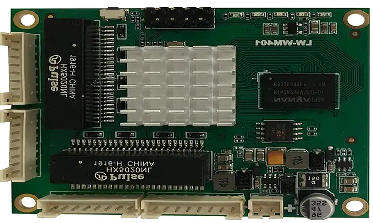
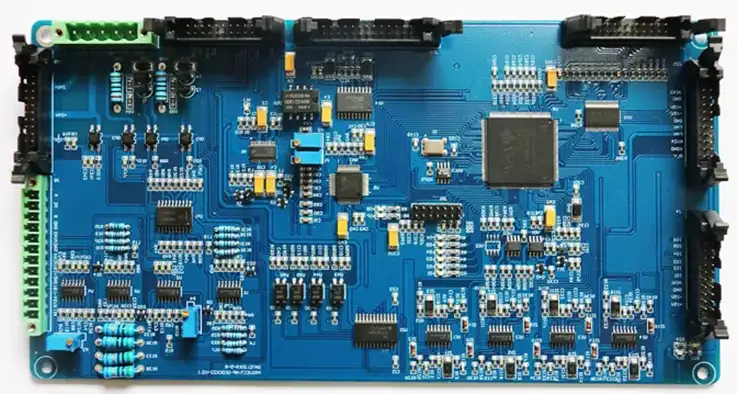
Printed Circuit Boards (PCBs) are fundamental components in nearly every electronic device. They serve as a platform for connecting electronic components, facilitating electrical connections through conductive pathways etched from copper sheets. Industrial PCBs are specially designed to meet the rigorous demands of various industrial applications. These boards are engineered to provide superior durability and reliability, ensuring they perform exceptionally in environments where precision and toughness are non-negotiable.
From automation systems that keep factories humming to renewable energy solutions harnessing the power of the sun, Industrial PCBs are everywhere, quietly powering the technology that drives progress. Imagine a manufacturing plant where every machine works in sync, thanks to the reliable performance of these circuit boards. That’s the essence of what Industrial PCBs bring to the table—precision, strength, and dependability in the face of demanding conditions.
The Importance of Industrial PCBs in Modern Technology
In today’s tech landscape, Industrial PCBs contribute significantly to boosting operational efficiency and overall performance. Their design, manufacturing, and assembly processes play a direct role in determining how well industrial equipment functions. Let’s break down some key aspects that highlight their importance:
Robustness Against Environmental Factors: Industrial PCBs are often exposed to harsh conditions—think temperature fluctuations, moisture, and vibrations. Using specialized materials like FR-4 or polyimide ensures these boards can withstand the test of time. For instance, in aerospace applications, a single failure in a PCB can lead to severe operational issues. That’s why aerospace-grade PCBs are designed with multiple layers and high-quality materials to ensure they stand strong against the elements.
Customization for Specific Applications: Every industry has unique needs. Industrial PCBs can be tailored for specific applications, whether it’s a complex design for a medical device or a simple layout for a basic automation task. The ability to customize boards not only enhances performance but also ensures compatibility with existing systems. For example, a food processing plant may require PCBs that are resistant to cleaning chemicals—this is where customization shines.
Facilitating Innovation: As technology continues to advance, so does the design and functionality of Industrial PCBs. With the rise of the Internet of Things (IoT) and smart devices, these boards are evolving to support new technologies, enabling connectivity and smarter operations in industrial settings. Consider a smart factory where machines communicate with each other in real time. It’s Industrial PCBs that make this seamless communication possible, driving efficiency and productivity.
Applications
To illustrate the versatility and application of Industrial PCBs, let’s take a look at a few examples:
| Industry | Application | PCB Type Used |
| Automotive | Engine control units | Multilayer PCBs |
| Telecommunications | Signal processing devices | High-frequency PCBs |
| Renewable Energy | Solar inverters | Rigid-flex PCBs |
| Medical Devices | Diagnostic equipment | Biocompatible PCBs |
These examples highlight how tailored PCB solutions can meet the specific demands of different sectors, ensuring that equipment operates effectively and reliably.
Key Considerations in Industrial PCB Design
Essential Design Principles for Industrial PCB
Designing an Industrial PCB involves much more than simply laying down traces; it requires a strategic and meticulous approach. Engineers need to navigate various factors to ensure the PCB meets the rigorous demands of industrial applications. Here’s a closer look at key design principles that every engineer should consider:
1.Component Placement:
Effective positioning of components is paramount. This not only minimizes the length of connections but also reduces the potential for interference, which is particularly important in high-speed applications. Consider a scenario where critical components, such as microcontrollers and sensors, are placed too far apart. This can lead to signal degradation and increased latency, impacting the overall performance. To combat this, engineers often use techniques like:
●Decoupling Capacitors: Placing these close to power pins to stabilize voltage.
●Avoiding Long Traces: Keeping connections short to enhance performance.
2.Trace Routing:
Thoughtful routing strategies play a significant role in maintaining signal integrity. Engineers must avoid crosstalk and electromagnetic interference (EMI) by following best practices in trace design:
●Controlled Impedance: Implementing controlled impedance for high-frequency signals to prevent reflections.
●Via Usage: Minimizing the number of vias in high-speed lines to maintain signal quality.
●For example, in an industrial automation system where speed is of the essence, improperly routed traces can lead to data corruption. A systematic approach to routing can mitigate such risks.
3.Layer Stack-Up:
Understanding the configuration of multilayer designs is fundamental. Engineers must carefully consider the stack-up to mitigate issues related to impedance and capacitance. Here’s a common layer stack-up for a four-layer PCB:
| Layer Number | Purpose |
| Layer 1 | Signal Layer (Top) |
| Layer 2 | Ground Layer |
| Layer 3 | Power Layer |
| Layer 4 | Signal Layer (Bottom) |
●Proper stack-up design helps maintain signal integrity and reduces noise, especially in high-density applications.
Overcoming Design Challenges in Industrial PCBs
Industrial environments pose distinct challenges, and crafting a PCB that can excel in these settings requires innovative thinking and foresight. Here are some critical considerations:
1.Thermal Management:
High temperatures can lead to performance degradation and component failure. Engineers must incorporate strategies like heat sinks, thermal vias, and thermal pads to effectively dissipate heat. For instance, a temperature-sensitive application such as a motor control board benefits from these features, ensuring components remain within operational limits. Utilizing simulation software can help predict thermal performance during the design phase.
2.Mechanical Stress:
Industrial applications expose PCBs to vibrations and shocks. To enhance durability, engineers should choose materials with high mechanical strength and apply appropriate design techniques. Some strategies include:
●Using Conformal Coating: Protects the PCB from environmental stressors and enhances mechanical stability.
●Reinforced Edges: Adding edge support to prevent flexing during operation.
3.Environmental Considerations:
Designing for harsh environments—like those involving moisture, chemicals, or extreme temperatures—requires careful selection of materials and protective coatings. For instance, using epoxy coatings can protect against moisture intrusion while ensuring signal pathways remain unaffected. Additionally, employing IP-rated enclosures can offer extra protection against environmental hazards.
Thermal and Signal Management in Industrial PCB Design
Managing thermal effects and ensuring signal integrity are two pillars of Industrial PCB Design. Engineers often implement strategies to tackle these challenges head-on:
●Differential Signaling: For sensitive data lines, using differential pairs can significantly reduce the impact of noise and improve signal quality. This is especially beneficial in high-speed communication applications, where even minor disruptions can lead to significant errors.
●Optimized Grounding Techniques: Establishing a solid grounding plan is essential for minimizing noise. Techniques such as using a ground plane can help provide a low-resistance path for return currents, ensuring cleaner signal performance.
●Thermal Expansion Considerations: Thermal expansion and contraction can impact component reliability. By accounting for different coefficients of thermal expansion (CTE) between the PCB material and components, engineers can design boards that resist stress and failure.
| Design Element | Recommended Practice | Impact on Performance |
| Thermal Management | Use of heat sinks and thermal vias | Reduces risk of overheating |
| Signal Integrity | Implement differential signaling | Enhances data transmission reliability |
| Grounding | Utilize ground planes and short return paths | Minimizes noise and interference |
Ready to take your Industrial PCB design to the next level? Embrace these practices, stay ahead of the competition, and make your mark in the industry! Your next great design could be just around the corner—don’t hesitate to innovate!
Industrial PCB Materials and Constructions
Material Selection in Industrial PCB Manufacturing
Choosing the right materials is foundational in Industrial PCB manufacturing. The choice of substrate, copper weight, and solder mask can profoundly influence the PCB’s performance, longevity, and overall effectiveness in various applications. Here’s a closer look at commonly used materials:
1.FR-4:
FR-4 is the go-to material for most PCBs due to its excellent mechanical and electrical properties. This epoxy resin laminate not only provides good insulation but also exhibits impressive resistance to moisture and chemicals. For example, in an industrial automation control system, FR-4 boards ensure reliable operation in potentially corrosive environments.
| Property | Value |
| Dielectric Constant | 4.5 – 5.0 |
| Glass Transition Temp | 130°C – 180°C |
| Moisture Absorption | 0.1% – 0.5% |
2.Polyimide:
For applications requiring flexibility and resistance to extreme temperatures, polyimide materials shine. These are particularly useful in aerospace and automotive industries where space is tight, and components must endure wide temperature fluctuations. The flexibility of polyimide PCBs allows them to bend and conform to various shapes without losing performance.
3.Metal Core PCBs:
Metal core PCBs are gaining traction in high-power applications where managing heat is essential. With a metal base—usually aluminum or copper—these boards excel in thermal conductivity, making them perfect for LED lighting and power supply circuits. For example, using a metal core PCB in an LED driver circuit allows for effective heat management, preventing thermal overload and extending the lifespan of components.
PCB Construction Techniques for Industrial Applications
Understanding various construction techniques helps manufacturers deliver tailored solutions. Here are key construction methods that enhance the reliability and functionality of Industrial PCBs:
1.Multilayer Construction:
Multilayer PCBs allow for increased circuit density, making them ideal for complex applications where space is at a premium. These boards stack multiple layers of circuits, which not only reduces the footprint but also enhances performance by minimizing signal loss and electromagnetic interference. For example, a medical device might utilize a multilayer design to accommodate multiple functions in a compact form factor.
| Layer Configuration | Benefits |
| 4-Layer | Good balance of complexity and size |
| 6-Layer | Enhanced routing options and signal integrity |
| 8-Layer and above | Suitable for high-performance applications |
2.Rigid-Flex PCBs:
Rigid-flex PCBs combine the benefits of rigid and flexible circuits, offering versatility in compact spaces. These constructions enable complex designs that can bend and flex without compromising reliability. Industries like consumer electronics often rely on rigid-flex designs to fit their products’ intricate shapes and functionalities. For example, a smartphone can integrate rigid-flex PCBs for its display and internal components, allowing for a sleek and efficient design.
How Many Types of Industrial PCB Circuit Boards?
Overview of Various Industrial PCB Types
The landscape of Industrial PCBs is vast, with several types designed to meet the diverse demands of various applications. Below is a closer look at the most common types:
1.Rigid PCBs:
Rigid PCBs are the backbone of industrial electronics, renowned for their durability and robustness. They maintain their shape and structure, making them ideal for applications where stability is key. With a solid substrate, these boards can support complex circuitry and high-density designs, suitable for everything from industrial automation controls to heavy machinery.
| Characteristics | Details |
| Thickness Range | Typically 0.2 mm to 3.2 mm |
| Copper Weight | 1 oz to 6 oz per square foot |
| Typical Applications | Controllers, power supplies |
2.Flexible PCBs:
Flexible PCBs are a fantastic solution when space is tight or when components need to bend and flex. Constructed from flexible plastic substrates, these boards can be tailored to fit specific applications. They’re commonly found in consumer electronics and medical devices, such as wearables that demand lightweight and compact designs.
| Characteristics | Details |
| Thickness Range | 0.05 mm to 0.5 mm |
| Bend Radius | As small as 1 mm |
| Typical Applications | Smartphones, medical devices |
3.Rigid-Flex PCBs:
Rigid-flex PCBs offer a clever blend of rigid and flexible designs, making them a go-to choice for unique applications. These boards feature both rigid sections and flexible areas, allowing for innovative designs while keeping structural integrity intact. They shine in industries like aerospace and automotive, where tight spaces and reliability are key concerns.
| Characteristics | Details |
| Layers | Typically 4 to 10 layers |
| Typical Applications | Aerospace controls, compact consumer devices |
Applications of Industrial PCB Types in Various Sectors
Each type of Industrial PCB finds its niche across various sectors, enhancing functionality and performance in different environments. Here’s how these PCBs are applied in key industries:
1.Automation:
Rigid PCBs dominate in automation systems, often found in controllers and sensors. These PCBs ensure precise control and monitoring of processes, such as in robotic assembly lines where reliability is crucial. For example, a factory automation control system might utilize rigid PCBs for their robust performance under continuous operation.
2.Medical Devices:
Flexible PCBs shine in the medical field, especially in wearable technology and imaging devices. These boards adapt to various shapes and are lightweight, making them perfect for applications like heart rate monitors or portable ultrasound machines. For instance, a wearable ECG monitor leverages flexible PCBs to conform to the user’s body, providing accurate readings without bulkiness.
3.Renewable Energy:
Rigid-flex PCBs are becoming increasingly popular in renewable energy applications, such as solar panels. Their adaptability allows for installation in diverse environments, maximizing efficiency. For example, in solar panel installations, rigid-flex designs can navigate complex shapes, ensuring that the electronic components are optimally positioned for maximum sunlight exposure.
Best Practices for Industrial PCB Manufacturing
Industrial PCB Manufacturing Process Overview
Manufacturing Industrial PCBs is quite the balancing act, requiring precision and expertise across various stages. Here’s a breakdown of the typical stages involved:
1.Design and Prototyping:
The journey kicks off with the design phase, where engineers dive into CAD (Computer-Aided Design) software to create detailed PCB layouts. Before going full steam ahead with production, prototypes are whipped up to validate functionality and manufacturability. This prototyping phase lets teams test the design against real-world conditions, ensuring that the final product doesn’t miss the mark without burning a hole in the budget.
| Step | Description |
| CAD Design | Create layouts using CAD tools |
| Prototype Testing | Validate designs with physical prototypes |
| Design Iteration | Refine designs based on prototype feedback |
2.Material Preparation:
Choosing the right materials is a big deal in Industrial PCB manufacturing. Think of it like picking the right ingredients for a recipe. Common materials include FR-4 for standard applications and polyimide for flexible designs. Once selected, materials are prepped, including cutting them down to size and giving them the right surface treatment.
3.Etching and Layering:
During the etching phase, copper layers are selectively removed to form the desired circuit pathways. This process uses a chemical approach that leaves behind the circuit design—almost like magic! In multilayer PCBs, layering techniques involve stacking and bonding layers, which is a must for complex designs where every inch counts
4.Drilling and Plating:
After etching, precise holes are drilled into the PCB for component leads. This step is followed by plating, where conductive materials coat the drilled holes, ensuring that the electrical connections are solid all the way through the board.
5.Solder Mask Application:
A solder mask is slapped on to protect the conductive pathways. This green (or sometimes other colored) layer works to prevent solder from bridging between traces during assembly, reducing the risk of short circuits and boosting reliability.
Custom Solutions in Industrial PCB Manufacturing
Customizing PCBs to meet specific client needs can elevate your offerings significantly. Whether it’s a unique shape, a tailored layer configuration, or specialized materials, collaborating closely with clients makes all the difference. These personalized solutions not only enhance the performance of the final product but can also lead to cost savings.
Case Study: A client in the automotive industry needed a custom-shaped PCB for a dashboard control module. By teaming up with the client to nail down their design specs, the manufacturing crew developed a tailored solution that fit like a glove in the vehicle’s design, leading to improved functionality and cutting down on manufacturing costs.
Automation and Quality Control in Industrial PCB Manufacturing
Jumping into automation has turned the Industrial PCB manufacturing game upside down. Automation amps up efficiency and consistency while cutting down on human error. Here’s the scoop:
1.Automated Assembly:
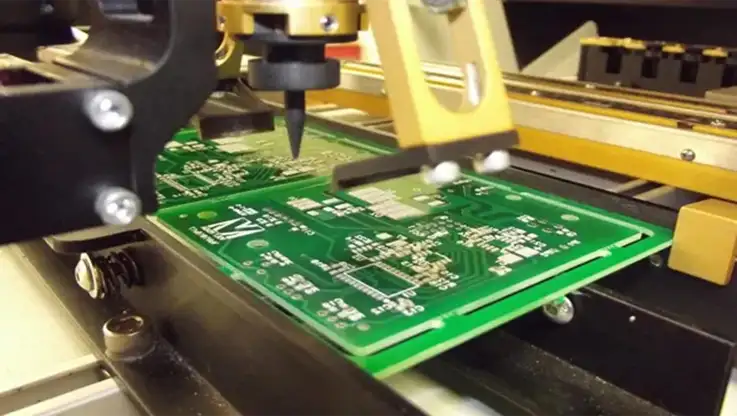
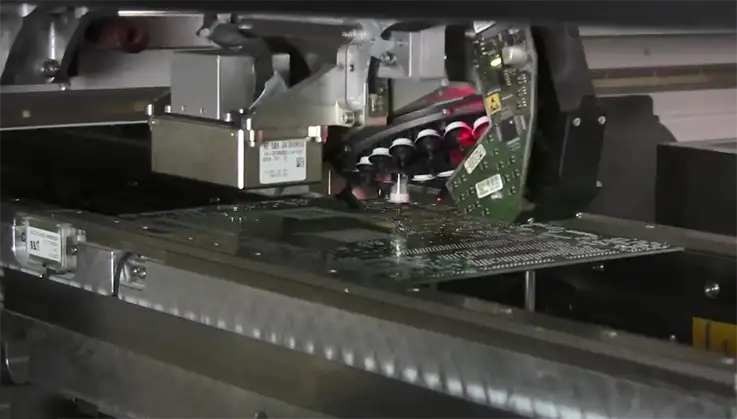
Automated assembly lines ensure precise placement of components, leading to better quality and faster production times. These machines can handle high-volume production runs without missing a beat.
2.Quality Control Measures:
Putting robust quality control measures in place is a must. This includes visual inspections, automated optical inspections (AOI), and functional testing. Automated testing systems can quickly spot defects, allowing for immediate fixes before the product hits the market.
| Quality Control Method | Description |
| Visual Inspection | Manual check for visible defects |
| Automated Optical Inspection (AOI) | Machine-assisted examination of PCBs |
| Functional Testing | Testing PCBs under operational conditions |
Best Practices in Industrial PCB Assembly
Key Steps in Industrial PCB Assembly
The Industrial PCB Assembly process is a well-orchestrated dance, where each step plays a pivotal part in crafting reliable electronic products. Here’s a closer look at the essential stages involved in this intricate process:
1.Solder Paste Application:
Think of solder paste application as laying down the groundwork. This step involves accurately dispensing solder paste onto specific pads where components will be positioned. It’s a crucial moment; too much or too little paste can lead to issues down the line. Automated stencil printers are commonly used to ensure that each pad gets just the right amount, helping to create a clean, professional finish.
2.Component Placement:
After the paste is in place, it’s time for the component placement phase. Automated pick-and-place machines take center stage here, expertly placing surface mount components onto the PCB with pinpoint accuracy. While these machines are the workhorses of the assembly line, skilled technicians often step in for manual adjustments when necessary, ensuring that each component sits just right. This teamwork can be the difference between a good board and a great one!
3.Reflow Soldering:
Once everything is positioned, the assembly hits the reflow soldering stage. In this process, the entire assembly is heated in a controlled manner, melting the solder and creating a solid connection between the components and the PCB. This step is like turning up the heat in the kitchen; it’s where everything comes together! Engineers carefully monitor the temperature profiles to avoid any potential pitfalls, like overheating, which could damage sensitive components.
| Step | Description |
| Solder Paste Application | Applying solder paste to designated pads |
| Component Placement | Automated placement with manual adjustments |
| Reflow Soldering | Heating assembly to create solder connections |
4.Inspection:
With the assembly complete, it’s time for a thorough inspection. Various inspection techniques come into play, from visual checks to automated optical inspection (AOI). Inspectors are on the lookout for misalignments or solder defects, which could lead to failures down the line. Think of it as giving your PCB a final once-over before it heads out the door.
Addressing Common Challenges in Industrial PCB Assembly
Challenges can arise during the Industrial PCB Assembly process, and being proactive is essential to keep things on track. Common issues like component misalignment and solder defects can throw a wrench in the works if not addressed quickly. Here are some strategies to tackle these hurdles:
1.Rigorous Inspection Processes:
Implementing stringent inspection protocols at each stage can help catch problems early. For example, conducting inline inspections after solder paste application and component placement can identify misalignments before they become a larger issue.
2.Advanced Inspection Techniques:
Techniques like X-ray inspection can provide an inside look at solder joints, particularly in multi-layer boards where visual inspections might not suffice. This tech-savvy approach allows manufacturers to ensure that connections are solid without missing a beat.
Surface Mount vs. Through-Hole Technology in Industrial PCB Assembly
When it comes to choosing between surface mount technology (SMT) and through-hole technology, it’s all about understanding the specific needs of the application. Each method has its own strengths that make it suitable for different scenarios.
1.Surface Mount Technology (SMT):
SMT stands out as the preferred option for high-density assemblies. Think of it like driving a compact car in a bustling city; it allows you to squeeze more components into tighter spaces, trimming down the overall size and weight of the board. Plus, with its automated processes, SMT speeds up assembly times significantly. It’s a great way to enhance your production flow!
2.Through-Hole Technology:
On the flip side, through-hole technology shines when it comes to applications demanding extra mechanical strength. Think of it as the heavy-duty truck that can carry a load without breaking a sweat. This method is perfect for components that will endure physical stress or harsh conditions, such as in military or aerospace applications.
| Technology Type | Advantages | Best Applications |
| Surface Mount Technology | Smaller size, faster assembly | High-density consumer electronics |
| Through-Hole Technology | Greater mechanical strength, stability | Military, aerospace, and industrial gear |
Integrating these best practices into your PCB assembly process can greatly boost the reliability and performance of your products. Every little detail matters! So, are you ready to tweak your assembly line and elevate your offerings? Adopt these strategies, and watch your efficiency take off!
Innovations and Trends in Industrial PCB Design and Manufacturing
Emerging Technologies in Industrial PCB Design
The landscape of Industrial PCB Design is undergoing a transformation, driven by emerging technologies that are reshaping how engineers approach their work.
1.Artificial Intelligence (AI) and Machine Learning:
Imagine having a smart assistant that not only helps with design but also predicts potential hiccups before they occur. AI and machine learning algorithms can analyze vast amounts of data, identifying design flaws and suggesting improvements based on past projects. For example, by simulating different design scenarios, engineers can test various configurations without the need for costly prototypes. This not only streamlines the design process but also enhances accuracy, making it easier to meet client specifications. It’s like having a crystal ball for your designs!
2.3D Simulation Tools:
These tools allow engineers to visualize and manipulate PCB layouts in a three-dimensional space. Instead of just looking at a flat representation, designers can explore how components interact and assess potential issues related to spacing and signal integrity. This innovative approach leads to more effective designs and fewer surprises during the manufacturing phase.
Advancements in Industrial PCB Manufacturing
As the saying goes, “You have to spend money to make money.” Innovations in Industrial PCB Manufacturing are helping companies do just that by cutting costs and improving quality.
1.Additive Manufacturing (3D Printing):
Additive manufacturing has made waves in the PCB industry, allowing for the creation of intricate geometries that traditional subtractive methods can’t achieve. By layering materials, manufacturers can produce complex circuit designs while minimizing material waste. For example, a company might utilize 3D printing to create a custom housing for their PCB, reducing production costs and lead times. This flexibility not only enhances design capabilities but also opens doors to rapid prototyping, giving businesses a competitive edge.
2.Advanced Materials:
The advent of new materials is revolutionizing PCB manufacturing. High-frequency laminates, flexible substrates, and thermal management materials are becoming the go-to choices for designers. These advancements help in enhancing the performance of PCBs in various applications, from telecommunications to automotive systems. For instance, using a flexible substrate can lead to thinner and lighter devices, which is a huge plus in consumer electronics.
Industry 4.0 and Smart Manufacturing in Industrial PCB Assembly
With the rise of Industry 4.0, smart manufacturing is taking the Industrial PCB Assembly process to new heights.
1.Integration of IoT (Internet of Things):
The buzzword around town is IoT, and for good reason! By embedding sensors and connectivity into manufacturing equipment, companies can gather real-time data on production processes. This integration enables manufacturers to monitor everything from assembly line speeds to equipment performance. For example, if a machine is running slower than usual, the system can automatically alert operators, allowing for immediate adjustments. It’s like having eyes everywhere, ensuring that everything stays on track.
2.Predictive Maintenance:
Rather than waiting for something to break down, manufacturers can use data analytics to predict when maintenance should occur. This proactive approach minimizes unplanned downtime and keeps operations humming along. By analyzing wear and tear data, companies can schedule maintenance during off-peak hours, ensuring that production continues seamlessly. Imagine a baseball team that can substitute players before they get injured — that’s the essence of predictive maintenance!
| Technology Type | Description | Benefits |
| Artificial Intelligence | Predicts design flaws and optimizes layouts | Increases accuracy and reduces prototyping costs |
| Additive Manufacturing | Builds PCBs layer by layer | Reduces waste and allows complex designs |
| IoT Integration | Monitors manufacturing processes in real-time | Enhances productivity and reduces downtime |
| Predictive Maintenance | Analyzes equipment data for maintenance timing | Prevents breakdowns and optimizes operations |
Wrapping Up: Key Insights for Industrial PCB Design and Manufacturing
As we gear up for an era marked by rapid technological advancements and a surging demand for efficient industrial solutions, the significance of thoughtfully designed Industrial PCBs cannot be understated. Whether you’re a seasoned engineer, a procurement specialist, or new to the field, getting familiar with the fundamentals of Industrial PCB Design, Manufacturing, and Assembly is where it’s at.
Ready to amp up your PCB know-how or need a boost with your projects? Don’t just sit there! Teaming up with seasoned professionals can offer insights tailored just for you. Embrace new technologies, keep your finger on the pulse of industry trends, and adopt innovative solutions to ensure your products don’t just blend in but truly shine in a bustling marketplace.
Let’s take this exciting journey together—there’s a bright future in Industrial PCB design and manufacturing, and you belong at the cutting edge. Get in touch today, and let’s turn those creative ideas into reality!
FAQ about Industrial PCBs
What are the primary applications of Industrial PCBs?
Industrial PCBs are utilized across various sectors, including automation, telecommunications, automotive, medical devices, and renewable energy. Their versatility and reliability make them suitable for both simple and complex electronic systems.
What materials are commonly used in Industrial PCBs?
Common materials for Industrial PCBs include FR-4 for standard applications, polyimide for flexibility, and metal core substrates for high-power applications that require efficient heat dissipation.
How does the design process impact the performance of Industrial PCBs?
The design process is crucial in determining a PCB’s performance. Key considerations such as trace routing, component placement, and thermal management directly affect signal integrity, reliability, and durability in industrial environments.
What are the challenges in manufacturing Industrial PCBs?
Manufacturing Industrial PCBs involves challenges such as maintaining high precision, managing material properties, and ensuring quality control. Overcoming these challenges often requires advanced technologies and meticulous processes.
What is the difference between surface mount technology (SMT) and through-hole technology?
SMT involves placing components directly onto the surface of the PCB, allowing for smaller and lighter designs. Through-hole technology requires drilling holes in the PCB for component leads, providing stronger mechanical connections, which is often preferred in high-vibration applications.

