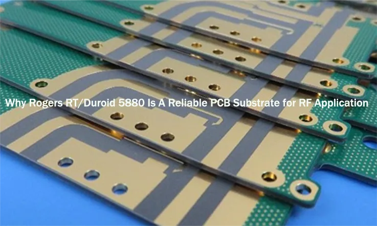
When it comes to high-frequency PCB design, the material you choose matters more than anything else. Rogers RT Duroid 5880 has proven itself as one of the most reliable and effective materials for high-performance circuit boards. From signal integrity to thermal stability, it ticks all the boxes, offering an unmatched balance of electrical properties and physical durability.
This guide delves into its applications in PCB manufacturing, including manufacturing processes, thermal stability, signal testing, and a comparison with other materials like Rogers 4000. It assists engineers in making the most suitable material choice for their specific project needs. At the same time, through an in-depth analysis of cost-performance ratio, manufacturing challenges, and long-term ROI, this article offers comprehensive technical insights for PCB design and high-frequency applications, helping our clients optimize cost while ensuring design quality.
Understanding Rogers RT Duroid 5880 in High-Frequency PCB Design
In high-frequency PCB design, where maintaining precise signal integrity is a consideration, Rogers RT Duroid 5880 has become a leading choice for applications that demand consistent performance. Whether it’s for telecommunications, aerospace, medical devices, or military systems, Rogers RT Duroid 5880 stands out for its low loss and thermal stability, making it a preferred material for designs that operate at high frequencies. This material’s ability to maintain signal fidelity under challenging conditions makes it a trusted solution for microwave and radio frequency circuits.
As the need for higher performance continues to grow, materials capable of managing the balance between signal quality and electrical efficiency become indispensable. Rogers RT Duroid 5880 provides a dependable solution for engineers and designers seeking to optimize signal transmission for a variety of demanding applications. Now, let’s explore the attributes that make Rogers RT Duroid 5880 an optimal material for high-frequency applications.
What Makes Rogers RT Duroid 5880 Ideal for High-Frequency Applications?
In high-frequency PCB design, signal integrity is a major concern. Rogers RT Duroid 5880 offers exceptional performance in this area, thanks to its low dielectric constant (Dk) and minimal loss tangent (Df). These characteristics ensure that signals remain intact, with minimal degradation, making this laminate a solid choice for RF circuits. It is commonly used in high-demand applications like 5G communication systems, aerospace electronics, and telecommunications. By using Rogers RT Duroid 5880, we can achieve reliable performance in environments where signal integrity is a priority.
Rogers RT Duroid 5880 features a low dielectric loss, allowing high-frequency signals to travel with minimal attenuation. This results in clearer and more accurate signal transmission, making it a suitable choice for microwave and radio frequency circuits. The material helps reduce signal distortion, ensuring that designs relying on stable and reliable signal integrity perform well. Whether in 5G systems or aerospace applications, Rogers RT Duroid 5880 maintains steady performance in various challenging environments.
Additionally, Rogers RT Duroid 5880 is engineered to perform effectively under various environmental factors such as high temperatures and humidity. This makes it a reliable material choice for applications that require consistent performance even under demanding conditions.
Rogers RT Duroid 5880: A Benchmark for High-Performance PCB Materials
In the competitive field of PCB materials, Rogers RT Duroid 5880 is widely regarded as a benchmark for high-performance designs, especially in high-frequency applications.Its high thermal stability allows it to perform well in challenging environments, where precise signal integrity is required. In applications like 5G, aerospace, and telecom, Rogers RT Duroid 5880 delivers consistent and reliable performance, helping our designers keep things running smoothly while maintaining signal clarity.
Its low dielectric loss allows high-frequency signals to remain strong and accurate as they pass through the circuit, making Rogers RT Duroid 5880 particularly effective for applications where signal precision and low attenuation are core. Widely used in advanced systems like aerospace, this material handles demanding environments with ease, delivering reliable performance even in the most challenging conditions.
Moreover, Rogers RT Duroid 5880 supports excellent thermal management, ensuring that performance remains consistent even under high-temperature conditions. This makes it well-suited for industries like military electronics and telecommunications, where durability and reliable performance are necessary.
How Rogers RT Duroid 5880 Enhances Design and Manufacturing Processes?
When designing and manufacturing PCBs for high-frequency systems, Rogers RT Duroid 5880 simplifies the process with its excellent machinability and consistent material properties. This allows for the creation of complex RF circuits with tight tolerances more easily.
Thanks to its easy handling in fabrication, whether through laser cutting, precision drilling, or fine trace formation, Rogers RT Duroid 5880 enables the creation of multi-layer PCBs for high-frequency applications without sacrificing signal quality. Therefore, whether for 5G infrastructure, aerospace designs, or medical electronics, Rogers RT Duroid 5880 supports the manufacturing needs of high-frequency circuit boards.
Furthermore, Rogers RT Duroid 5880 also helps minimize production failures, ensuring that products align with specifications from the outset. This reliability streamlines the production process, reducing turnaround times and increasing efficiency, especially in complex projects where precision matters most.
Why Choose Rogers RT Duroid 5880 for High-Frequency PCB Applications? (H2)
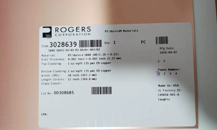
When high-frequency PCB designing, material choice is everything. If you’re working on designs for RF applications, telecommunications, or aerospace technologies, you need a material that handles high-frequency signals with precision, durability, and reliability. Rogers RT Duroid 5880 is a standout option, offering unmatched electrical properties, low loss, and thermal stability that make it an best solution for high-frequency circuits.
But what exactly sets Rogers RT Duroid 5880 apart from other materials used in high-speed PCB design? Let’s explore its exceptional properties and how they contribute to its success in RF applications, microwave communications, and beyond.
Outstanding Electrical Properties of Rogers RT Duroid 5880
When working with high-frequency circuits, the material’s electrical properties directly impact performance. Rogers RT Duroid 5880 offers a low dielectric constant (Dk) and low loss tangent (Df), which help minimize signal loss and maintain signal clarity. This makes it well-suited for demanding applications like 5G communication, satellite technology, and aerospace electronics, where even small deviations in signal integrity can lead to issues in functionality.
The material ensures minimal signal degradation over long distances, ensuring that your circuit performs at its best even in demanding conditions. Here’s a comparison of the electrical properties of Rogers RT Duroid 5880:
| Property | Value (Typical) | Significance |
| Dielectric Constant (Dk) | 2.2 ± 0.02 | Provides low signal loss for high-frequency applications |
| Loss Tangent (Df) | 0.0004 | Minimizes energy loss in high-speed and RF circuits |
| Volume Resistivity | 2*107 | Prevents conductive failures and supports reliability over time |
| Surface Resistivity | 3*107 | Enhances stability and reduces electrical degradation |
Impedance Control in Rogers RT Duroid 5880 for High-Speed Circuits
Impedance control is a core factor in maintaining the performance of high-speed circuits. For any circuit operating at high frequencies, impedance must be controlled to avoid issues such as signal reflections or signal degradation. Rogers RT Duroid 5880 provides exceptional impedance stability for RF PCBs and high-frequency applications.
When designing for high-speed circuits, ensuring consistent impedance is a must. Rogers RT Duroid 5880 allows us to control impedance accurately, thus preserving signal integrity even in the most demanding applications.
Here’s a comparison of impedance control in Rogers RT Duroid 5880 and other PCB materials:
| Material | Dielectric Constant (Dk) | Loss Tangent (Df) | Impedance Stability |
| Rogers RT Duroid 5880 | 2.2 ± 0.02 | 0.0004 | High |
| FR-4 (Standard PCB) | 4.5 | 0.02 | Moderate |
| PTFE (Teflon) | 2.2 | 0.0002 | Very High |
Thermal Management with Rogers RT Duroid 5880 for Extreme Environments
Effective thermal management is a consider concern in high-frequency PCB design. When high-speed circuits operate, they can generate considerable heat, which can impact performance and reliability. Rogers RT Duroid 5880 excels in its thermal stability, ensuring that your PCB can handle heat and continue to perform reliably even in extreme conditions.
The thermal properties of Rogers RT Duroid 5880 help it perform well under high temperatures, preventing thermal cycling and thermal expansion from affecting the circuit. Whether designing for high-power RF circuits or components used in space exploration, the material can withstand the stress of high temperatures while maintaining its mechanical and electrical properties.
Here’s a quick look at the thermal properties of Rogers RT Duroid 5880 in comparison to other materials commonly used in PCB manufacturing:
| Property | Value (Typical) | Significance |
| Thermal Conductivity | 0.2 W/m·K | Effective heat dissipation prevents overheating |
| Coefficient of Thermal Expansion (CTE) | 16 ppm/°C | Maintains stability under fluctuating temperatures |
| Glass Transition Temperature (Tg) | 280°C | Performs reliably even at high temperatures |
With Rogers RT Duroid 5880, we can trust that our high-frequency circuits will continue to operate efficiently, even in environments with significant thermal stress.
Key Advantages of Rogers RT Duroid 5880 in PCB Manufacturing
When selecting materials for PCB manufacturing, the choice of material impacts the overall performance of high-frequency circuits. Rogers RT Duroid 5880 stands out due to its specialized characteristics tailored to RF applications. This material delivers reliable signal fidelity, high-speed performance, and low loss, making it an ideal fit for industries requiring precise PCB designs, such as telecommunications, aerospace, and military electronics.
Since these properties, Rogers RT Duroid 5880 improves both PCB design and manufacturing processes. Let’s delve deeper into the benefits of using Rogers RT Duroid 5880 and how it helps streamline the manufacturing process.
High-Speed Performance and Low Loss with Rogers RT Duroid 5880
For RF circuit designs, signal integrity is a must, and Rogers RT Duroid 5880 excels in this area. With a dielectric constant (Dk) of 2.2 and an ultra-low loss tangent (Df) of 0.0004, this material minimizes signal loss, ensuring high-frequency signals remain strong and accurate. It’s ideal for long-range, high-speed PCB designs, reducing distortion and interference while maintaining consistent performance. So, if you’re working on telecommunications, aerospace, or other advanced technologies, Rogers RT Duroid 5880 guarantees that your signals stay clear and your system performs at its best.
The material’s low dielectric constant also ensures minimal signal dispersion, which enhances the transmission speed of data in high-speed RF circuits. These properties are especially suited to modern 5G networks, microwave communications, and other high-frequency electronics that rely on rapid and stable signal transmission.
Improved Signal Fidelity and Reliability in Critical Applications
Signal fidelity is a non-negotiable requirement for RF circuits that demand consistent, long-term performance, and Rogers RT Duroid 5880 meets this need with precision. Its stable electrical properties help keep signal integrity intact, ensuring reliability over time. This makes it a preferred material in industries like aerospace, defense, and medical technologies, where every bit of signal matters to ensure the system operates as intended. For designs that can’t afford to lose even the slightest bit of accuracy, Rogers RT Duroid 5880 delivers the consistency and durability required to keep things on track.
The material’s low moisture absorption guarantees that the dielectric constant remains consistent, even when exposed to moisture or fluctuating temperatures. This contributes to the reliability of signals, ensuring long-lasting performance in a variety of environmental conditions.
Durability and Long-Term Performance of Rogers RT Duroid 5880 in Harsh Conditions
In high-frequency PCB designs used in extreme environments, Rogers RT Duroid 5880 provides solid durability. It is particularly effective in high-temperature conditions where less stable materials might degrade. With a glass transition temperature (Tg) of 280°C, Rogers RT Duroid 5880 maintains its properties in extreme conditions, allowing the material to stay robust over time without significant changes in performance.
Moreover, the low coefficient of thermal expansion (CTE) of Rogers RT Duroid 5880 reduces mechanical stress in high-temperature environments, promoting longer-lasting PCB reliability. This thermal stability contributes to the long-term reliability of PCBs, making it an suitable choice for industries like military and aerospace, where temperature fluctuations can be extreme.
Designing High-Performance PCBs with Rogers RT Duroid 5880
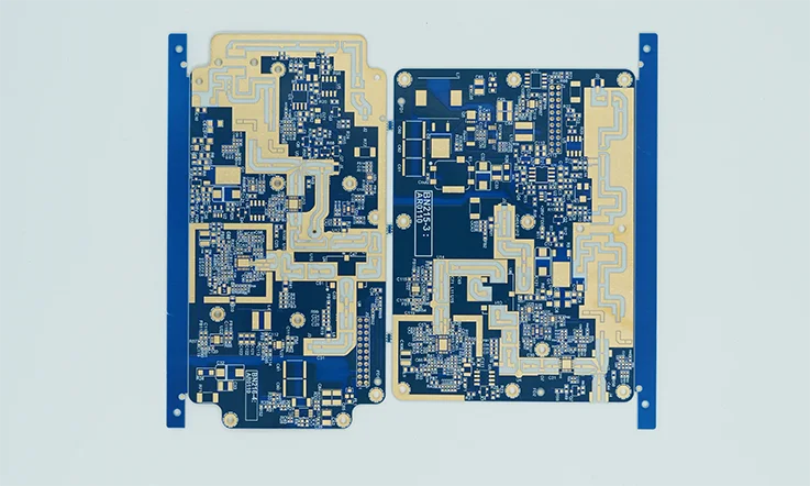
When designing high-frequency PCBs, one must select materials that ensure stable performance under demanding conditions. Rogers RT Duroid 5880 is widely recognized for its superior ability to meet the needs of RF circuit designers and manufacturers looking for reliable performance in high-speed applications. By leveraging the unique properties of Rogers RT Duroid 5880, many engineers can optimize PCB designs to meet the challenges posed by advanced technologies in 5G communication, aerospace, and military electronics.
Now, let’s take a closer look at some of the best practices that can help PCB designers maximize the potential of Rogers RT Duroid 5880 while addressing common challenges in high-frequency circuit design.
Best Practices for Designing High-Frequency PCBs with Rogers RT Duroid 5880
Designing high-frequency PCBs requires a comprehensive understanding of the material’s electrical properties, as well as the ways to optimize its performance in RF circuits. When using Rogers RT Duroid 5880, consider these best practices for achieving precision:
1.Accurate Impedance Control: For high-frequency signals, maintaining the proper impedance is essential to avoid signal loss and reflection. With Rogers RT Duroid 5880, we can accurately control impedance across a wide frequency range, ensuring smooth transmission without unwanted signal degradation.
2.Minimize Signal Loss: The low loss tangent of Rogers RT Duroid 5880 is a huge advantage in reducing signal attenuation. By utilizing Rogers RT Duroid 5880 in your high-speed PCB design, the material’s ability to preserve the strength of signals is maximized, leading to more reliable performance in some applications.
3.Thermal Management: Rogers RT Duroid 5880 offers excellent thermal conductivity, making heat dissipation easier to manage in high-power RF circuits. For high-frequency PCB designs, we should focus on efficient heat distribution to prevent overheating and maintain stable performance in demanding environments.
By integrating these best practices into the PCB design process, we can ensure that Rogers RT Duroid 5880 delivers optimal performance in high-frequency applications such as 5G systems and aerospace communication networks.
Challenges in High-Frequency Design and How Rogers RT Duroid 5880 Solves Them
Designing high-frequency circuits presents its own set of challenges that can compromise signal quality and performance if not addressed properly. Some of the common issues faced by PCB designers include signal loss, impedance mismatch, and thermal instability. Here’s how Rogers RT Duroid 5880 helps solve these problems:
1.Signal Loss: Rogers RT Duroid 5880 helps minimize signal loss in high-frequency PCB designs. Its low loss tangent reduces attenuation, allowing signals to travel more efficiently without significant degradation. This makes it an excellent choice for high-speed applications, where maintaining signal integrity directly impacts performance.
2.Impedance Mismatch: One of the challenges of high-frequency design is achieving consistent impedance control across the entire PCB. Rogers RT Duroid 5880 excels in providing consistent impedance across various frequency ranges. This property ensures that signals do not experience reflection or distortion, even at higher frequencies.
3.Thermal Instability: Rogers RT Duroid 5880 excels at managing the heat produced by high-frequency circuits. The high thermal stability of Rogers RT Duroid 5880 makes it an excellent choice for applications exposed to high temperatures, as it minimizes thermal expansion and improves the overall durability of the PCB.
Optimizing Rogers RT Duroid 5880 for Advanced RF Circuitry
To make the most out of Rogers RT Duroid 5880, we need to focus on optimizing the material’s properties for advanced RF circuitry. Here’s how you can make Rogers RT Duroid 5880 work for high-speed applications:
1.Tailoring Layer Thickness: Rogers RT Duroid 5880 is available in a variety of thicknesses. Our PCB designers can adjust the thickness of the material to meet specific signal performance requirements. By carefully choosing the appropriate thickness, it’s possible to control the dielectric constant and loss tangent, further optimizing the material for RF circuit design.
2.Using Multilayer Designs: To improve performance in advanced RF systems, multilayer PCBs are often necessary. Rogers RT Duroid 5880 can be integrated into multilayer structures with other materials to create high-performance RF circuit designs. This approach allows for enhanced signal propagation and minimal cross-talk between layers.
3.Designing for Frequency Scalability: Rogers RT Duroid 5880 offers excellent frequency scalability in RF circuit designs. Whether working with 5G technology, satellite communications, or microwave circuits, Rogers RT Duroid 5880 ensures that signal integrity is maintained across a broad spectrum of frequencies, from low GHz to high-end microwave bands.
By optimizing Rogers RT Duroid 5880 for advanced RF applications, we can develop high-speed PCB solutions that perform well in the most demanding environments.
Rogers RT Duroid 5880 in PCB Manufacturing: Process and Innovations
Rogers RT Duroid 5880 is widely recognized as a leading material for high-frequency applications in PCB manufacturing. Known for its exceptional consistency throughout the entire fabrication process, it ensures optimal performance in challenging environments. Therefore, understanding how to effectively utilize Rogers RT Duroid 5880 during production is key to achieving a product that meets performance goals. With its reliable properties and outstanding material characteristics, this laminate provides the stability required to thrive in demanding industries.
In this section, we’ll explore how Rogers RT Duroid 5880 is processed during PCB fabrication, the latest advancements in processing techniques, and how we overcome the typical challenges faced when working with this high-performance material.
Optimizing the Manufacturing Process for Rogers RT Duroid 5880
Efficient PCB fabrication ensures that high-speed circuits designed with Rogers RT Duroid 5880 maintain optimal performance and reliability. The manufacturing process for Rogers RT Duroid 5880 requires several precise steps to make sure the material meets expectations in demanding environments. To maximize the material’s potential, consider these optimizations in your process:
1.Controlled Lamination: During PCB fabrication, the lamination process requires precise control over temperature and pressure to ensure proper bonding and minimize defects when using Rogers RT Duroid 5880. By optimizing the lamination cycle, consistent dielectric properties can be maintained, which helps preserve signal integrity in high-frequency applications.
2.Precision Drilling and Etching: Since Rogers RT Duroid 5880 has a unique composite structure, precision drilling is necessary to ensure the accuracy of vias and component holes. High-speed PCB designs require that the etching process is highly controlled to avoid damaging the material’s delicate layers while maintaining consistent impedance and signal fidelity.
3.Thermal Profiling: The thermal properties of Rogers RT Duroid 5880 require precise thermal profiling throughout the manufacturing process to avoid thermal stress. Optimizing the cooling phase helps prevent distortion and ensures the high-temperature stability that Rogers RT Duroid 5880 offers in real-world conditions.
Advanced Processing Techniques for Rogers RT Duroid 5880
For PCB fabrication, utilizing advanced processing techniques is necessary when working with Rogers RT Duroid 5880, a material tailored for high-speed circuits and RF applications. Here are some innovative methods that enhance PCB manufacturing when working with Rogers RT Duroid 5880:
1.Laser Drilling: For high-frequency PCBs, where accuracy is a must, laser drilling offers a reliable method for creating small, precise vias. This technique helps keep the signal integrity of Rogers RT Duroid 5880 intact. It helps maintain the high impedance control required for RF applications, ensuring that signal transmission remains strong and clear.
2.High-Precision Lamination: Advanced lamination techniques like vacuum lamination allow Rogers RT Duroid 5880 to be bonded more effectively. This method supports designs that require precise signal routing and low-loss performance, making it an effective choice for high-performance applications..
3.Automated Inspection: With advanced automated inspection techniques, we can monitor the integrity of Rogers RT Duroid 5880 throughout the PCB fabrication process. Automated optical inspection (AOI) systems help detect defects early, allowing for fast corrections and ensuring that the final product meets high-quality standards.
Challenges and Solutions in Rogers RT Duroid 5880 PCB Manufacturing
While Rogers RT Duroid 5880 offers many advantages, working with it in PCB manufacturing presents several challenges. Understanding these challenges—and how to overcome them—can help ensure a smoother process and a higher-quality end product. Below are some common manufacturing challenges and solutions when working with Rogers RT Duroid 5880:
1.Material Variability: One challenge with Rogers RT Duroid 5880 is the potential for slight material variability, which can affect impedance control and signal integrity. To address this, PCB manufacturers can implement strict quality control protocols at every stage of the fabrication process. Regular material testing and process monitoring can minimize these variations and ensure consistency throughout production.
2.Difficulties with Etching: The high-frequency material properties of Rogers RT Duroid 5880 can make it more challenging to etch precisely, particularly when creating fine traces for RF circuits. By using advanced etching techniques and precise mask alignment, these challenges can be mitigated, ensuring clean and precise trace formation without compromising the material’s signal performance.
3.Thermal Issues: As Rogers RT Duroid 5880 is used in high-speed circuits, heat dissipation becomes a concern. During the PCB manufacturing process, careful control of thermal profiles ensures that the material maintains its heat resistance throughout both production and operation. The solution lies in integrating effective thermal management systems, such as heat sinks or thermal vias, to ensure optimal thermal stability in the final product.
Considerations for Using Rogers Duroid 5880 Laminate in Multilayer PCB Fabrication
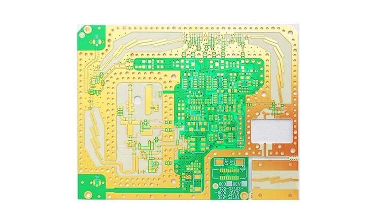
When working with multilayer PCB fabrication, Rogers Duroid 5880 is a top choice for designs that demand high-frequency signal integrity and solid thermal performance. However, successfully integrating this high-performance laminate into your process requires a detailed approach and expertise. Below are several factors to consider when incorporating Rogers Duroid 5880 into your multilayer PCB design and manufacturing process to ensure it performs as expected.
Dielectric Constant (Dk): Precision in Signal Integrity
The dielectric constant (Dk) of Rogers Duroid 5880 affects the performance of high-speed circuits. With a low Dk of approximately 2.2, it’s particularly suited for RF and microwave applications. In multilayer PCB designs, achieving consistency across all layers helps maintain stable impedance control and ensures reliable signal transmission throughout the design.
For your design, ensure that the dielectric constant is consistent throughout the layers of your multilayer PCB. Any discrepancy can lead to signal reflection, which affects overall performance. When routing transmission lines, consider using controlled impedance techniques to maintain signal quality and prevent unwanted signal loss.
| Material | Dielectric Constant (Dk) | Use Case |
| Rogers Duroid 5880 | 2.2 | High-speed, high-frequency signal integrity |
Copper Cladding: Choosing the Right Thickness for Optimal Performance
The selection of copper cladding directly impacts the current-carrying capacity and thermal management of your multilayer PCB. For Rogers Duroid 5880, copper cladding options typically range from 0.5 oz to 2 oz per square foot. The right choice of copper weight will depend on the current demands and the thermal performance required for your design.
●For low-power, high-frequency designs, a 0.5 oz copper cladding might suffice.
●For powerful applications such as RF amplifiers or high-frequency circuits, you might opt for 1 oz or 2 oz cladding to support higher currents and improve heat dissipation.
| Copper Weight | Use Case | Current Capacity |
| 0.5 oz/sq. ft | Low-power, high-frequency | Low current |
| 1 oz/sq. ft | General RF circuits | Moderate current |
| 2 oz/sq. ft | High-power, high-frequency | High current |
Layer Stackup Design: Ensuring Impedance Control and Signal Integrity
To ensure optimal performance in a multilayer PCB, designing the layer stackup carefully is a must. Rogers Duroid 5880 is commonly used as the core material, placed between prepreg or other laminate layers. The layer stackup should be crafted to achieve the desired impedance characteristics, while also reducing crosstalk and minimizing signal interference.
Here are some tips to optimize the layer stackup for Rogers Duroid 5880:
●Place power and ground planes adjacent to each other to minimize noise and optimize decoupling.
●Use high-frequency traces and ensure they are routed symmetrically to minimize inductive and capacitive coupling.
●Consider the trace width and spacing based on the dielectric thickness to maintain controlled impedance.
Thermal Considerations: Managing Heat Effectively
Even though Rogers Duroid 5880 is known for its thermal stability, managing heat in your design is still a must. High-power components and circuits can generate significant heat, which can impact signal integrity and shorten the lifespan of your PCB. Proper thermal management, like using heat sinks or thermal vias, helps ensure that your design stays in good shape and performs well over time.
Here are a few strategies for managing thermal dissipation in multilayer PCBs using Rogers Duroid 5880:
●Thermal vias can be strategically placed to transfer heat away from critical components.
●Heat sinks or copper pours help to spread the heat across a larger area, preventing localized overheating.
| Thermal Solution | Benefit |
| Thermal Vias | Helps in heat transfer from the component to other layers |
| Copper Pours | Spreads heat, reducing thermal hotspots |
| Heat Sinks | Effective for high-power components |
Fabrication Techniques: Specialized Processes for Optimal Results
Due to its unique properties, Rogers Duroid 5880 demands specialized fabrication techniques. When working with this material, ensure that your PCB manufacturer has the right expertise. Some of considerations for fabrication include:
●Controlled impedance routing to ensure signal integrity.
●Precise drilling for vias, as the laminate is relatively stiff and requires high precision.
●Plating and lamination processes must be meticulously controlled to avoid material degradation during the manufacturing process.
Always communicate your design requirements to your PCB manufacturer, ensuring they have experience with Rogers Duroid 5880 to achieve the desired performance.
Design for Manufacturability (DFM): Streamlining the Production Process
Designing with Rogers Duroid 5880 for multilayer PCB fabrication requires careful attention to detail. Make sure your design files are spot on, with precise layer stackup details, drill files, and fabrication notes. Clear documentation will eliminate confusion during production and ensure the PCB is manufactured to meet top-tier standards.
Effective DFM practices lead to a smoother manufacturing process and improve the overall reliability of the final product.
Cost Considerations: Balancing Performance and Budget
Rogers Duroid 5880 is a high-performance laminate, and while it offers excellent signal integrity and thermal stability, it comes with a higher price point than standard materials like FR-4. When designing your multilayer PCB, carefully evaluate the overall budget, considering:
●The specific requirements of your high-frequency application.
●The long-term ROI (Return on Investment) provided by the superior performance of Rogers Duroid 5880 in demanding environments.
While it might be tempting to choose cheaper materials, the added performance benefits of Rogers Duroid 5880 can offset the higher upfront costs, especially in high-performance applications.
Quality Control and Testing for Rogers RT Duroid 5880 PCBs
In the production of high-performance PCBs, achieving consistent quality is a major priority. Rogers RT Duroid 5880 is a preferred material for high-frequency applications due to its stable properties, which require precise control throughout the manufacturing process. Let’s take a closer look at how these PCBs are tested to maintain the level of precision required in industries like telecommunications, aerospace, and defense.
Ensuring Consistent Quality in Rogers RT Duroid 5880 PCB Production
The foundation of producing top-notch Rogers RT Duroid 5880 PCBs lies in thorough quality control during fabrication. It all starts with raw material inspection, where every laminate sheet is checked for thickness uniformity and dielectric consistency. Further checks include:
●Visual Inspection: During this phase, the PCB undergoes visual inspections to identify any defects in the copper, ensuring smooth, defect-free surfaces.
●Dimensional Measurements: The PCB’s dimensions are carefully measured to ensure accuracy, as even minor discrepancies can lead to performance issues in high-frequency circuits.
These inspections help verify the initial quality of the material and guide the process of fabricating highly reliable boards that perform well in high-frequency environments.
Visual Inspection Quality Control Process-
| Step | Process Description | Accepted Tolerance | Methodology |
| Copper Surface Check | Inspect for visible scratches, pits, or contaminants. | No visible defects | Visual Inspection |
| Dimensional Check | Measure the PCB size and copper layer thickness. | ±0.05mm | Micrometer/Caliper |
Thermal and Electrical Testing of Rogers RT Duroid 5880 PCBs
After the fabrication of the PCB, thermal and electrical tests are conducted to verify that the board will perform reliably under the conditions it will face in its end-use applications.
Thermal testing helps evaluate how a PCB performs under high temperature conditions, which is particularly relevant for applications exposed to heat. These tests include:
●Thermal Cycling: This test simulates the temperature changes the PCB may encounter, ensuring it can handle rapid temperature shifts without degradation.
●Heat Dissipation: The board is tested to see how effectively it manages heat, preventing overheating in high-power applications.
Electrical Testing ensures the board’s performance by evaluating:
●Impedance Matching: High-frequency designs require precise impedance to maintain signal integrity. This test ensures that the PCB exhibits the required impedance consistency.
●Signal Integrity: Measurement of how signals propagate through the PCB without loss or distortion.
Thermal and Electrical Testing Results-
| Test Type | Process Description | Target Performance | Test Results |
| Thermal Cycling | Subject PCB to temperature cycles from -40°C to +150°C. | No physical degradation | Passed (0 Defects) |
| Impedance Matching | Measure the impedance across different sections of the PCB | ±10% of target impedance | Within Range |
| Signal Integrity | Check signal degradation during high-frequency tests | Loss < 0.5dB | 0.3dB Loss |
Testing for High-Frequency Applications with Rogers RT Duroid 5880
For high-frequency applications, ensuring a PCB can manage fast signal speeds with minimal interference is a top consideration. Rogers RT Duroid 5880 stands out for maintaining solid signal integrity and minimal loss in high-speed environments. To verify these characteristics, the following tests are performed:
●Return Loss Testing: This test checks the amount of signal that is reflected back due to impedance mismatches. It helps identify any potential signal interruptions that may occur during signal transmission.
●Insertion Loss Testing: This measures the loss of signal as it travels through the PCB, an essential metric for maintaining clear communication in RF applications.
●Electromagnetic Interference (EMI) Testing: EMI testing is essential to ensure that the PCB does not emit or suffer from excessive interference, which could disrupt its operation.
High-Frequency Testing Results-
| Test Type | Process Description | Target Performance | Test Results |
| Return Loss | Measure the reflected signal due to impedance mismatch. | < -15dB | -18.2dB |
| Insertion Loss | Evaluate signal attenuation through the PCB. | < -0.5dB | -0.3dB |
| EMI Testing | Ensure PCB does not emit or receive unwanted interference. | < 30dB | Passed (29dB) |
Cost vs. Performance in Rogers RT Duroid 5880 PCB Manufacturing
In PCB manufacturing, finding the right balance between cost and performance is a deciding factor. Rogers RT Duroid 5880 is known for delivering outstanding performance in high-frequency applications. We can fine-tune this material to achieve cost-effectiveness without compromising on performance quality.
Understanding the Cost-Performance Ratio of Rogers RT Duroid 5880
Evaluating the cost-performance ratio of Rogers RT Duroid 5880 helps us determine its value in PCB production. While this material may involve a higher upfront cost, its advantages in terms of performance, reliability, and durability make it a solid investment.
Here’s a breakdown of the cost-performance dynamics:
1.Material Cost: Rogers RT Duroid 5880 is a premium-grade substrate, and its cost reflects the superior properties it offers. Although higher in price compared to standard materials, its performance justifies the investment in applications requiring precision and stability.
2.Performance: The material’s low loss tangent and excellent thermal stability ensure minimal signal degradation, making it suitable for applications that demand high reliability under varying conditions.
3.Efficiency: Using Rogers RT Duroid 5880 in PCB fabrication often leads to streamlined production processes, reducing the likelihood of errors and ensuring consistent quality.
Cost vs. Performance Comparison (Traditional PCB vs. Rogers RT Duroid 5880)-
| Parameter | Traditional PCB | Rogers RT Duroid 5880 |
| Material Cost | Lower | Higher |
| Signal Loss | Higher | Lower |
| Temperature Stability | Lower | Higher |
| Durability | Moderate | High |
Long-Term Investment Benefits of Rogers RT Duroid 5880 in PCB Production
The long-term investment benefits of Rogers RT Duroid 5880 are significant. Its durability and reliability lead to lower lifecycle costs and higher return on investment (ROI) compared to standard materials.
●Reduced Downtime: High-quality materials such as Rogers RT Duroid 5880 reduce the likelihood of unexpected downtimes due to performance issues, particularly in high-stakes environments where reliability is non-negotiable.
●Maintenance Efficiency: Fewer repairs and maintenance are required due to the material’s enhanced durability and performance stability.
●Extended Lifespan: With superior thermal and mechanical properties, this material offers a longer operational lifespan, reducing the frequency of PCB replacements.
ROI of Using Rogers RT Duroid 5880 (5-Year Analysis)-
| Parameter | Traditional PCB | Rogers RT Duroid 5880 |
| Initial Material Cost | Lower | Higher |
| Downtime Cost (Annually) | $40,000 | $8,000 |
| Maintenance Costs | Higher | Lower |
| Total ROI (5 Years) | $160,000 | $120,000 |
Making the Right Economic Decision for High-Frequency PCB Projects
Choosing the appropriate material for high-frequency PCB projects involves a thorough understanding of cost and performance trade-offs. Rogers RT Duroid 5880 offers a robust solution for high-performance requirements where reliability and precision are non-negotiable.
By focusing on its cost-performance benefits, wes can ensure that our investment delivers consistent, high-quality results in the long term.
Comparison of Rogers RT/Duroid 5880 and Rogers 4000 Laminates
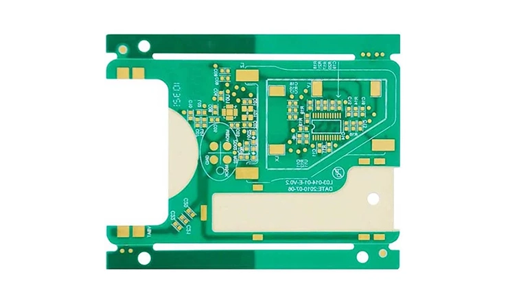
When choosing materials for high-frequency PCB designs, two of the most commonly discussed options are Rogers RT/Duroid 5880 and Rogers 4000 laminates. Both are engineered for advanced applications that demand superior performance, but they cater to different project needs based on factors like dielectric constant, thermal stability, and signal integrity. Let’s dive into the key differences and help you decide which material might suit your next project.
Dielectric Constant (εr): Balancing Performance for High-Frequency Designs
The dielectric constant of a PCB material is a main factor that directly impacts signal integrity and impedance control. Here’s how Rogers RT/Duroid 5880 and Rogers 4000 compare:
●Rogers RT/Duroid 5880: With a low dielectric constant of around 2.20, RT/Duroid 5880 offers excellent signal integrity, making it good for high-frequency circuits where low signal loss is a priority. This is particularly beneficial in applications like RF/microwave components, where maintaining the purity of the signal is a must.
●Rogers 4000: This laminate offers a higher dielectric constant that ranges between 3.38 and 3.66. Its higher value is especially useful for designs that need controlled impedance, such as power amplifiers, antennas, and radar systems. Its use ensures that the signal is transmitted efficiently without interference or distortion.
| Material | Dielectric Constant (εr) | Signal Integrity |
| Rogers RT/Duroid 5880 | 2.20 | Excellent (Low Loss) |
| Rogers 4000 | 3.38–3.66 | High (Controlled Impedance) |
Dissipation Factor: Signal Quality and Efficiency
The dissipation factor indicates how much energy is lost during the transmission of electrical signals. This factor is particularly noticeable in high-frequency applications, where signal degradation can affect performance and lead to issues with data integrity.
●Rogers RT/Duroid 5880: As we known that its low dissipation factor, RT/Duroid 5880 excels in environments where high-quality signal transmission is non-negotiable. This helps ensure that even in applications with high-frequency data, signal loss is minimized.
●Rogers 4000: Similar to RT/Duroid 5880, Rogers 4000 also offers a low dissipation factor, ensuring reliable signal propagation over long distances and under various operational conditions.
| Material | Dissipation Factor | Signal Loss |
| Rogers RT/Duroid 5880 | Low | Minimal Loss |
| Rogers 4000 | Low | Low Loss |
Thermal Stability: Choosing the Right Material for Heat Resistance
When working with high-speed circuits or components exposed to extreme thermal conditions, the thermal stability of your PCB material becomes a must consideration. Here’s how these materials perform under heat stress:
●Rogers RT/Duroid 5880: While it offers good thermal stability, it is best suited for applications with moderate temperature ranges. It provides adequate performance under high frequencies but may face challenges under more extreme temperature conditions.
●Rogers 4000: Designed with enhanced thermal stability, Rogers 4000 is the better option for high-temperature environments. It can endure harsher conditions, making it suitable for industries such as aerospace, defense, and other demanding high-frequency applications.
| Material | Thermal Stability | Max Temperature Resistance |
| Rogers RT/Duroid 5880 | Good | Up to 180°C |
| Rogers 4000 | Enhanced | Up to 200°C |
Applications: Tailoring Materials to Specific Needs
Both Rogers RT/Duroid 5880 and Rogers 4000 are used in high-frequency applications, but the best material for your project depends on its specific requirements. Here’s a breakdown of typical uses for each laminate:
●Rogers RT/Duroid 5880: This laminate is widely utilized in high-frequency designs that require stable signal transmission. Common uses include amplifiers, filters, RF/microwave components, and antennas. It’s a good fit for industries such as wireless communication, automotive radar, and aerospace, where reliability and solid performance are sought after.
●Rogers 4000: The higher dielectric constant of Rogers 4000 makes it a better fit for applications requiring controlled impedance. It is used in base stations, power amplifiers, and radar systems. Its high thermal stability makes it especially suitable for the aerospace, defense, and wireless communication sectors.
| Material | Typical Applications |
| Rogers RT/Duroid 5880 | Amplifiers, Antennas, Aerospace, Wireless Communication |
| Rogers 4000 | Power Amplifiers, Base Stations, Radar Systems |
FAQ & Rogers RT Duroid 5880
1. Can Rogers RT Duroid 5880 be used for multilayer PCBs?
Yes, Rogers RT Duroid 5880 can be incorporated into multilayer PCBs, typically as a core material, ensuring excellent performance in high-speed designs.
2. Is Rogers RT Duroid 5880 compatible with traditional PCB fabrication methods?
Yes, though it requires specialized handling for precise signal integrity and thermal management.
3. How does Rogers RT Duroid 5880 perform in high-temperature environments?
It offers good thermal stability, making it suitable for applications with elevated temperature requirements.
4. How does Rogers RT Duroid 5880 affect signal loss in PCB designs?
Due to its low dissipation factor, Rogers RT Duroid 5880 minimizes signal loss, ensuring efficient signal propagation in high-speed circuits.
Our services
Rogers PCB Laminates & Series

