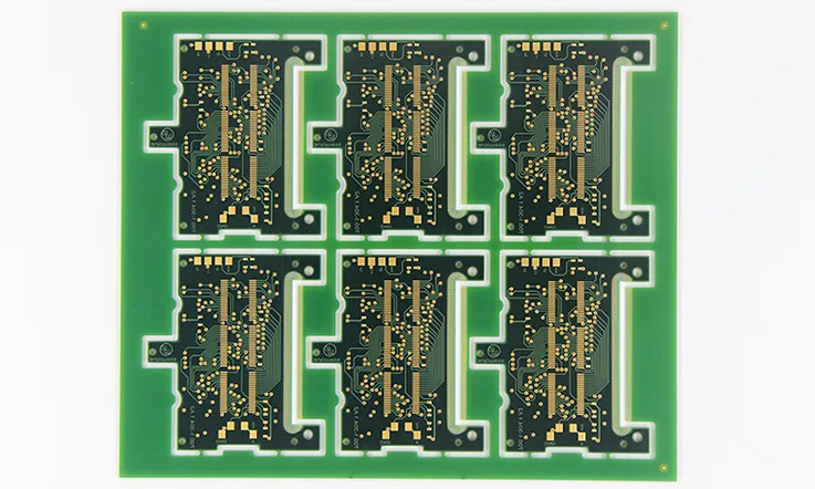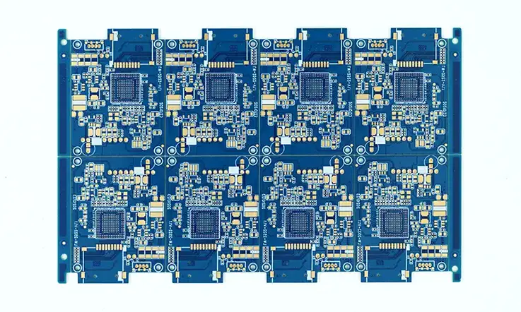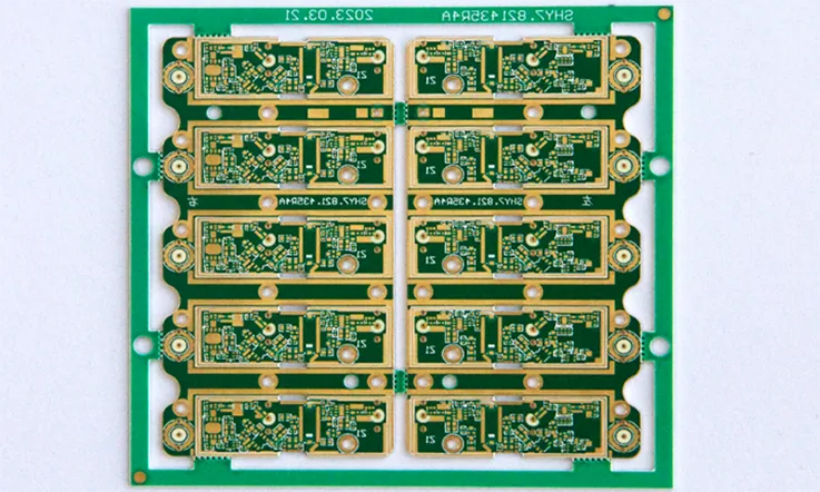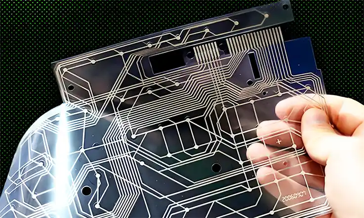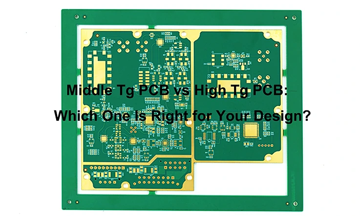
Printed circuit boards (PCBs) have come a long way since their inception, evolving in materials and performance to match the demands of modern electronics. Among the many considerations when choosing PCB materials, the glass transition temperature (Tg) stands out as crucial, especially when considering performance in various environments. But how do you choose between middle Tg and high Tg materials? Let’s break it down.
Tg: The Backbone of PCB Durability
The glass transition temperature (Tg) refers to the point where a PCB’s substrate begins to soften when exposed to heat. Essentially, it’s the temperature at which the board transitions from a rigid, glass-like state to a more flexible, rubbery one. Now, this doesn’t mean the board melts – rather, its mechanical stability starts to decline.
In the context of PCBs, a middle Tg typically falls between 130°C and 150°C, while high Tg PCBs exceed 170°C. The higher the Tg, the better the PCB can handle thermal stress, making it essential for high-temperature applications. For instance, a board with Tg170 might be a lifesaver if you’re working on designs like automotive electronics or high-speed processors.
Why You Need to Care About Tg?
You might be thinking, “Why should I care about Tg unless I’m working on extreme designs?” The truth is, as electronic components shrink and power increases, even consumer electronics can face severe thermal stresses.
Think of it like this: when you’re pushing a PCB to its limits, maybe in a tight enclosure or high-power environment, your board’s Tg becomes the difference between success and failure. In situations like that, a middle Tg material could easily overheat and fail, causing downtime and product recalls.
Middle Tg vs High Tg PCBs: Key Differences
Comparing Electrical Insulation and Heat Resistance
While middle Tg PCBs like Tg150 offer solid electrical insulation properties, they pale in comparison to their high Tg counterparts. The thermal expansion of high Tg materials is much lower, meaning they can better withstand higher operational temperatures without deforming or causing issues like delamination—a critical point if you’re designing PCBs for more demanding use cases.
Please find the following table:
| Characteristic | Middle Tg (Tg130-Tg150) | High Tg (Tg170+) |
| Thermal Stability | Adequate for consumer electronics | High thermal reliability |
| Dimensional Stability | Moderate, some risk of warping | Excellent, minimal warping |
| Dielectric Constant | Higher, more signal degradation | Lower, better signal integrity |
| Typical Applications | Consumer electronics, smart devices | Automotive, 5G, high-speed designs |
At a glance:
Middle Tg PCBs (Tg130-Tg150): Typically used in consumer electronics, home appliances, and other devices that don’t experience extreme thermal stress.
High Tg PCBs (Tg170+): Found in high-performance electronics like automotive control units (ECUs), 5G base stations, and high-frequency applications.
High Tg materials offer improved dimensional stability, which means less warping and better reliability. Moreover, they tend to have a lower dielectric constant (Dk) and loss tangent (Df), which is vital for maintaining signal integrity in high-speed designs.
Therefore, this is where Tg170 materials excel. With enhanced dimensional stability and moisture resistance, high Tg materials reduce the risk of signal loss or electrical insulation breakdown, ensuring reliable operation even in high-temperature environments. For applications that demand performance over prolonged exposure to heat, this makes high Tg PCBs the go-to option.
High Tg Materials in PCB Manufacturing
The Benefits of High Tg PCBs for Extreme Environments
When you’re designing for extreme environments, it’s a bit like gearing up for a tough mountain trek—you need gear that can handle the roughest conditions without flinching. The same goes for high Tg PCBs (printed circuit boards with a glass transition temperature of 170°C or higher). These boards are engineered to take on intense thermal cycling, high operating temperatures, and mechanical stresses, making them ideal for industries where durability and long-term reliability are non-negotiable.
Tough as Nails in Harsh Settings
For industries like aerospace, automotive, and military, where electronics are subjected to punishing conditions—think engine compartments in cars or aircraft control systems—high Tg PCBs bring stability. In these high-heat scenarios, using a standard PCB can be a bit like taking a pocket umbrella into a hurricane—it’s just not going to hold up. High Tg materials, on the other hand, provide the backbone to endure those constant temperature swings, ensuring that your circuits don’t warp, delaminate, or fail prematurely.
The beauty of high Tg materials is that they reduce the risk of thermal expansion. In simple terms, when things heat up, regular PCBs tend to expand, causing internal stresses that lead to cracks or material fatigue. High Tg PCBs, however, stay cool under pressure—literally—allowing your electronics to last much longer in demanding environments.
5G and High-Performance Electronics-
As we step into the future of 5G and high-speed communication networks, high Tg PCBs are becoming the go-to choice. Why? It’s all about signal integrity. High-frequency signals are highly susceptible to loss, and when boards heat up, that risk increases. High Tg materials keep the dielectric constant (Dk) and loss tangent (Df) in check, minimizing signal loss and preventing attenuation—a big win for systems that need to transfer data quickly and accurately, like 5G base stations and data centers.
Braving the Heat in Automotive Electronics-
Take a look under the hood of a modern car, and you’ll find a host of electronics managing everything from engine performance to emission control. High Tg PCBs are a necessity here, as automotive systems operate in one of the most thermally challenging environments out there. The engine bay, where temperatures can spike to over 125°C, is no place for ordinary PCBs. Instead, high Tg materials step in, resisting thermal degradation while providing consistent electrical performance.
Thermal Management: The Secret Weapon
In high-performance applications, thermal management is a huge deal. Thermal vias—those tiny, strategically placed holes filled with conductive material like copper—help transfer heat away from sensitive components to heat sinks or other dissipative layers. When you pair thermal vias with high Tg materials, you’re essentially building a heat-resistant fortress around your circuits. The thicker copper layers also play a key role, offering improved thermal conductivity, which is like having an efficient cooling system built right into your board.
This combination of smart design and resilient materials ensures that high Tg PCBs perform efficiently, even when pushed to their limits in harsh environments.
Why High Tg PCBs Are Worth It?
Sure, high Tg PCBs might come with a heftier price tag, but it’s a classic case of “you get what you pay for.” Whether you’re designing high-speed routers, satellite systems, or mission-critical aerospace components, investing in a high Tg board means you’re choosing reliability over the long haul. These boards stand up to the test, making them a no-brainer for applications where durability, heat resistance, and consistent performance are the name of the game.
Advanced Thermal Management Techniques for High Tg PCBs
When dealing with high Tg PCBs, one of the first things designers need to consider is thermal management. At elevated temperatures, circuits are prone to signal degradation, increased resistance, and even catastrophic failure. This is where high Tg materials save the day.
Advanced techniques like thermal vias, heat sinks, and copper planes can enhance heat dissipation and keep the PCB cool. For instance, in automotive electronics, where high-power components generate intense heat, these designs are key to ensuring reliable performance.
Thermal Vias and Heat Sinks: The Unseen Heroes of Heat Management
In high-performance PCB applications, thermal management isn’t something you can overlook. One of the unsung heroes in this area is the thermal via, which essentially acts like a highway for heat, directing it away from sensitive components to places where it can dissipate safely—typically toward a heat sink or through dissipative layers.
The placement of thermal vias is no accident; it’s all about strategy. Engineers position them near components that are prone to overheating—think power ICs or processors—to ensure the heat has a direct path to escape. This is especially critical in high Tg PCBs, where components are often pushing the boundaries of what a PCB can handle in terms of thermal stress.
Now, let’s talk copper. The thickness of copper layers in your PCB plays a massive role in heat dissipation. Thicker copper layers create a more efficient pathway for heat to move, reducing the risk of hotspots forming in densely packed areas. In designs where heat is a major concern, using a 2 oz. copper layer instead of the standard 1 oz. makes a noticeable difference. It’s kind of like swapping a garden hose for a fire hose—more volume, less resistance, better cooling.
Impedance Control Techniques: Keeping Signals Sharp in High-Frequency Designs
When it comes to high-frequency designs, like those found in 5G networks or automotive radar systems, one of the biggest headaches for engineers is maintaining signal integrity. This is where impedance matching comes into play. High Tg materials lend themselves well to high-frequency applications because they maintain dimensional stability even under high thermal and electrical loads. That stability reduces the chances of crosstalk and signal attenuation—two culprits that can really mess up your design if left unchecked.
But here’s the kicker: if your impedance isn’t matched properly, you’re going to see reflections in your signal. These reflections can cause a loss in data integrity, leading to dropped packets or even failure in mission-critical systems. That’s not something you can risk in industries like automotive or telecommunications, where reliability is the name of the game.
For multi-layer PCBs, especially those used in 5G or automotive ECUs, impedance control is even more delicate. You have to balance the needs of signal speed with power integrity. Matching impedance in these designs ensures that your high-speed signals maintain their integrity across different layers without running into unnecessary interference.
High Tg materials have a lower loss tangent, meaning they don’t absorb as much of the signal as traditional materials. This helps preserve signal strength over longer distances and at higher frequencies, making them ideal for 5G base stations or radar systems in modern vehicles. In short, proper impedance control, backed by the right material selection, can make or break the performance of your PCB design.
Simulation Tools for Thermal and Signal Integrity
Before sending your PCB design to the manufacturer, using simulation software can save you a world of hurt by identifying potential issues early in the process. Below are some practical tips to ensure you’re getting the most out of your simulations.
Tip 1: Choose the Right Software
There’s a variety of PCB simulation tools on the market, such as ANSYS, Altium Designer, and Mentor Graphics. The right choice depends on the complexity of your design. For high Tg PCBs, it’s worth investing in simulation tools that provide in-depth analysis of thermal dissipation, mechanical stress, and signal integrity.
Tip 2: Focus on Thermal Dissipation
One of the key parameters to simulate in high Tg PCB designs is thermal dissipation. You can model how heat is transferred through the PCB using tools like ANSYS, which allows you to tweak the copper thickness, thermal vias, and heat sink placement to optimize heat management. This is especially critical in high-performance applications where even slight temperature deviations can degrade performance over time.
Tip 3: Test for Signal Integrity
For high-speed designs, simulating signal integrity is non-negotiable. Altium Designer, for instance, enables impedance matching simulations to ensure that your traces are optimized for the high frequencies common in 5G or automotive radar systems. By simulating crosstalk and signal attenuation, you can adjust the layout to mitigate these issues before they wreak havoc on your final design.
Tip 4: Simulate Mechanical Stability
In environments where your PCB will face mechanical stresses, like in automotive or industrial electronics, simulating the mechanical stability of high Tg materials is crucial. Many PCB simulation tools allow you to model the effects of vibration, shock, and thermal cycling on your design to ensure that your board will hold up over time without failure.
Tip 5: Use the Data for Cost-Effective Decisions
Simulation doesn’t just prevent design flaws—it can also help you make more cost-effective decisions. By identifying areas where you can use thinner copper layers or reduce component placement density without sacrificing performance, you’ll save money on both materials and manufacturing costs.
Let’s face it – no one wants to discover signal attenuation or thermal issues after production. With tools like these, you can identify potential weak points and optimize both impedance control and thermal performance before the first prototype is even fabricated.
Who’s Using Middle and High Tg PCBs?
Automotive Electronics: Why High Tg PCBs Dominate?
In automotive systems, particularly within the engine control units (ECUs), temperatures can exceed 100°C regularly. This puts immense pressure on the PCB to maintain signal integrity and withstand repeated thermal cycling. Using high Tg materials, with their superior thermal reliability, ensures that the boards won’t degrade, crack, or lose performance over time.
In the high-stakes world of automotive electronics, high Tg PCBs have quietly revolutionized the way components like engine control units (ECUs) handle the relentless heat under the hood. When you’re talking about temperatures spiking above 125°C, middle Tg materials simply can’t cut it anymore. They tend to warp or break down, leading to more frequent failures and higher costs in the long run. Switching to high Tg PCBs brings a whole new level of reliability to the table.
For example, a top-tier auto manufacturer made the switch from a Tg150 PCB to a Tg170+ for their ECU design. What they saw was not just a reduction in thermal stress, but also a notable increase in the lifespan of their circuits by 20-30%. This change wasn’t just about boosting performance; it was also about keeping maintenance costs down. Less warping means fewer replacements, translating to a direct reduction in service costs over time. Over a year, this company saved an estimated $50,000 just by using a material that could withstand higher temperatures with ease.
Imagine this: You’re driving your car on a hot day, the engine is running hotter than usual, but your vehicle’s electronics don’t miss a beat. That’s the power of high Tg PCBs. They’re built to take the heat, quite literally, without sacrificing performance.
Performance Boosts in Harsh Environments
Beyond longevity, high Tg PCBs offer enhanced mechanical stability, which is a game-changer for handling vibrations from road conditions or engine movement. In middle Tg materials, continuous mechanical strain can lead to microcracks or signal degradation over time. But with high Tg PCBs, you’re looking at superior structural integrity that holds up, even in the roughest conditions. This stability isn’t just theoretical either—it has been demonstrated in real-world performance tests, where high Tg PCBs outperformed their middle Tg counterparts by 25%.
Telecommunications: The 5G Revolution
With 5G technology pushing the boundaries of data transmission, high Tg PCBs are crucial to maintaining signal integrity in these high-speed networks. Because 5G infrastructure relies on high-frequency signals, the low dielectric constant of high Tg materials makes them ideal for reducing signal loss and improving overall transmission efficiency.
Jumping over to 5G infrastructure, high Tg PCBs are fast becoming the backbone of this rapidly growing sector. With 5G networks pushing more data at higher frequencies, you need materials that can handle both the heat and the electrical demands. Middle Tg PCBs start to choke under these requirements—signal loss and crosstalk become rampant, affecting overall performance.
One of the major players in the telecom space recently upgraded their 5G base station designs from middle Tg PCBs to high Tg PCBs, specifically Tg170+. The results were eye-opening. Not only did they see a 15% improvement in signal integrity, but they also managed to cut down on the heat generated by the high-speed processing units. This reduction in heat led to fewer cooling requirements, meaning smaller heat sinks and less energy used for temperature control. In a year, this change amounted to a 15% reduction in energy costs, which, when scaled across multiple stations, turned into millions in savings.
Signal Integrity and Thermal Management for Next-Gen Networks
In 5G, signal integrity is king, and high Tg materials like Tg170+ provide just what’s needed to keep that integrity intact over long distances. The low dielectric loss of these materials means that high-frequency signals can travel further without losing steam, allowing 5G networks to maintain the ultra-fast speeds they’re known for. Pair that with improved thermal management and you’ve got a material that’s truly cutting-edge in the tech world.
Consumer Electronics: Where Middle Tg Still Shines?
Not all designs require the high performance of Tg170 materials. For products like smartphones, smart home devices, and wearable tech, middle Tg materials (Tg130-Tg150) strike a perfect balance between performance and cost. While these devices may face some thermal stress, it’s not enough to justify the higher price of a high Tg PCB.
Middle Tg for Consumer Electronics
Take, for instance, consumer electronics, where heat levels remain well within manageable limits. Devices like smart home products, toys, or even low-power chargers rarely experience the high operational temperatures that would necessitate a high Tg board. Here, middle Tg materials are perfect—providing stable performance, sufficient heat resistance, and cost savings. Why break the bank on high Tg PCBs when middle Tg does the job?
Think of it like buying a winter coat for a mild fall day. You don’t need all the thermal insulation that comes with a high Tg material when your project is only going to see moderate temperatures at best.
Perfect for Budget-Sensitive Designs
Middle Tg PCBs are also a go-to for products where the primary focus is budget. Take the lighting industry, for example. LED strips and light panels—especially in residential or retail settings—typically do not endure extreme heat. Designing with middle Tg materials allows manufacturers to keep costs low without sacrificing reliability, making this a popular choice for large-scale lighting applications.
From fitness trackers to basic home automation devices, designers can leverage middle Tg materials to create robust, dependable electronics without splurging on unnecessary features.
Common Misconceptions About Tg: Setting the Record Straight
There’s a pervasive myth that high Tg PCBs are always the superior choice. But the truth is, if your design doesn’t operate in high-temperature environments, you’re just throwing money away. High Tg materials come with a higher price tag, and while they excel in thermal stability, middle Tg materials are more than sufficient for the vast majority of consumer applications.
On the flip side, many assume that middle Tg PCBs aren’t reliable, but in reality, they perform exceptionally well in everyday electronics, from televisions to smart gadgets.
What’s Next for High Tg PCBs?
As industries like 5G, autonomous vehicles, and IoT devices demand ever more sophisticated materials, the push for even higher Tg materials (Tg180+) is driving innovation in both signal transmission and thermal management.
Tg180+ for 5G Base Stations
One of the hottest areas of research in PCB materials right now is the development of Tg180+ materials for use in 5G base stations. The faster signal transmission required by 5G networks generates a significant amount of heat, which can degrade the performance of traditional materials. By switching to Tg180+ materials, designers can ensure better signal integrity at higher frequencies, particularly in high-power components where crosstalk and signal attenuation could become major issues.
These materials also offer improved dimensional stability and thermal conductivity, making them perfect for applications where precision and performance are non-negotiable. As 5G continues to expand, the demand for higher Tg PCBs will likely increase, with designers needing to balance cost and performance while ensuring that their boards can withstand the rigors of high-speed data transmission.
Autonomous Vehicles and IoT Devices
In the realm of autonomous vehicles and IoT, the need for high Tg materials is equally pressing. Autonomous driving systems require reliable and durable PCBs that can handle the constant stress of thermal cycling, vibrations, and exposure to harsh environments. By using Tg180+ materials, designers can create PCBs that offer not only thermal resilience but also mechanical durability, ensuring that these complex systems remain reliable even in the most demanding conditions.
As for IoT devices, where miniaturization and high-frequency performance are the norm, the use of advanced high Tg materials helps ensure signal stability across long transmission ranges. Devices that need to process large amounts of data in real-time—such as smart sensors and wearable tech—benefit immensely from the improved heat dissipation and signal integrity offered by these materials.
How to Choose the Right Tg Material for Your PCB Project?
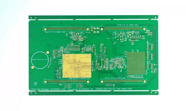
When choosing the ideal Tg (glass transition temperature) for your PCB design, there’s no one-size-fits-all solution. Engineers need to consider several factors to ensure the chosen material fits the project’s specific requirements. Let’s walk through the key steps in making an informed decision.
Step 1: Evaluate Operating Temperature
The first thing you’ll want to assess is the expected operating temperature of your PCB. If your design will be exposed to high temperatures, whether from environmental factors or heat-generating components, then opting for a high Tg PCB (above 170°C) may be the safest bet. High Tg materials provide better thermal stability, allowing the PCB to perform without risk of delamination or warping. On the flip side, if your project doesn’t involve extreme heat, you might be able to save some money by using middle Tg materials (130-170°C).
Step 2: Consider Frequency Demands
In designs that require high-frequency signal transmission, such as 5G infrastructure or high-speed computing systems, you’ll need to pay close attention to signal integrity. High Tg materials tend to perform better in these contexts because they maintain dimensional stability under the heat generated by fast signal transmissions, reducing the risk of signal loss and crosstalk. For projects requiring superior impedance control, high Tg is often the go-to choice.
Step 3: Understand Mechanical Stress
If your PCB will face significant mechanical stress—perhaps in an automotive application where vibrations are a concern—selecting a high Tg material can enhance the overall mechanical stability of your design. These materials offer better rigidity and resilience in harsh environments. In contrast, middle Tg materials may suffice for simpler, less mechanically demanding applications, such as consumer electronics.
Step 4: Budget Constraints
Cost is always a consideration. High Tg materials are generally more expensive due to their enhanced performance capabilities. If budget constraints are a major factor and the project requirements don’t demand top-tier performance, middle Tg may provide a solid balance between cost and capability. However, in critical systems, cutting corners on Tg can lead to higher failure rates and more frequent field returns.
Step 5: Industry Standards and Compliance
Certain industries, like aerospace, automotive, and medical devices, often require PCBs to meet specific regulatory standards. High Tg materials are frequently the recommended choice in these industries due to their ability to withstand extreme conditions over time. Always check whet
So, Why High Tg Matters for Your Next Design?
At the end of the day, switching to high Tg PCBs isn’t just about chasing numbers on a spec sheet. It’s about creating designs that work better, last longer, and save you money. Whether you’re dealing with the relentless heat of an engine bay or the high-frequency demands of a 5G base station, high Tg PCBs provide the thermal and signal integrity needed to keep things running smoothly. As the saying goes, “If it ain’t broke, don’t fix it,” but if you’re still using middle Tg materials, you might just be courting trouble down the line. So why not future-proof your designs with high Tg?
High Tg PCBs are not just a step up—they’re a leap forward in performance and efficiency!
Wrapping Up
Striking the Right Balance Between Middle and High Tg Materials
In the ever-evolving electronics industry, the choice between middle Tg and high Tg materials is not to be taken lightly. Whether you’re working on automotive electronics, telecom devices, or industrial systems, understanding the benefits and limitations of these materials will guide your decision-making process. By selecting the right Tg material for your PCB, you ensure the best performance for your specific application, while also keeping costs in check. And that, my friends, is the sweet spot we’re all after!

