Selecting the right material for high-frequency PCB design has a direct impact on signal integrity, power transmission efficiency, and long-term stability. Taconic TLY-5A, a PTFE-based glass-reinforced laminate, stands out due to its low dielectric constant (Dk), minimal dissipation factor (Df), and outstanding thermal reliability, making it suitable for 5G networks, millimeter-wave radar, aerospace systems, military radar, and AI-driven hardware.
With several high-frequency PCB materials available—such as Rogers, Isola, and Panasonic laminates—Taconic TLY-5A has gained attention for its consistent impedance control, predictable signal behavior, and stable manufacturing tolerances. However, working with PTFE-based substrates requires a thorough understanding of drilling, etching, and lamination techniques. Ignoring proper fabrication methods can lead to signal degradation, layer delamination, or mechanical failures.
This guide covers optimal PCB stack-ups, material characteristics, processing challenges, and performance comparisons with other high-frequency laminates. For those working on RF circuits, high-speed digital systems, 5G infrastructure, or next-generation AI computing, taking a closer look at how Taconic TLY-5A can enhance designs is a must.
Why Taconic TLY-5A?
In high-frequency PCB design, many assumptions cloud the decision-making process. While many materials are advertised as “low-loss,” there’s a lot more to consider. Let’s take a closer look at Taconic TLY-5A and see how it compares in real-world applications for RF circuits, microwave systems, and high-speed digital applications.
“Low-Loss” vs. “Ultra-Low-Loss” – Where Taconic TLY-5A Stands?
When we talk about “low-loss,” it’s easy to assume that any material labeled that way will perform well. But there’s a difference between low-loss and ultra-low-loss materials, especially when you push the design to higher frequencies. Taconic TLY-5A keeps dielectric loss to a minimum, even under high-frequency conditions. While other materials claim to be low-loss, Taconic TLY-5A excels by offering minimal loss tangent (Df) across a wide frequency range. It’s like picking a car that performs well on highways and city streets—it’s reliable when pushed to its limits. This stability in performance gives human confidence when designing circuits for RF applications, as it helps avoid signal degradation that could affect high-speed communication systems.
Compared to other materials, Taconic TLY-5A delivers steady low-loss performance, making it ideal for 5G and microwave designs where maintaining clear signals matters.
Why Some High-Frequency PCB Designs Fail – The Hidden Challenges?
Ever run into a design that looks great on paper but falters when built? The reality is, many high-frequency designs don’t perform as expected because of overlooked issues during the design and manufacturing process. Let’s look at some common pitfalls that often go unnoticed:
●Dielectric Constant (Dk) Variation – Fluctuations in Dk can lead to impedance mismatches and signal reflection that reduce performance.
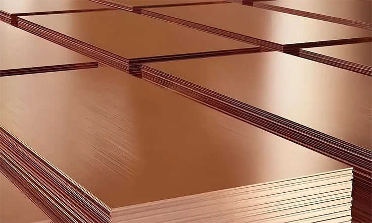
●Copper Foil Surface Roughness – Rough surfaces on the copper can cause additional signal loss, especially in high-speed signals.
●Layer Bonding Inconsistencies – If layers aren’t properly bonded during manufacturing, the PCB could exhibit poor performance under stress.
With Taconic TLY-5A, you get a material that maintains stable Dk values and ensures a consistent copper interface, which helps minimize these issues. This consistency supports achieving reliable performance in high-frequency PCBs.
The Real Impact of Dielectric Constant Variability on RF Performance
The stability of dielectric constant (Dk) is a central concern for engineers working with high-speed digital and RF circuits. Small changes in Dk can lead to significant issues, especially at higher frequencies where impedance mismatches become more pronounced. In designs where signal integrity is crucial, any variation in Dk can disrupt the timing of signals, leading to reduced system performance.
With Taconic TLY-5A, we can benefit from consistent Dk across a range of frequencies. This stability ensures that impedance remains controlled, which is necessary for maintaining signal integrity in microwave systems, 5G networks, and satellite communications. Thanks to its low Dk variation, Taconic TLY-5A helps avoid issues that might otherwise affect signal transmission or data reliability.
Advantages of Taconic TLY-5A in High-Frequency PCB Applications
In high-frequency PCB design, choosing the right material can significantly impact performance. Taconic TLY-5A excels in delivering dependable results in RF circuits. With characteristics like a low dielectric constant and solid signal integrity, it supports a range of high-speed applications. Let’s take a closer look at how Taconic TLY-5A performs and why it could be a solid choice for high-frequency designs.
Low Dielectric Constant (Dk) and Low Dissipation Factor (Df) for RF Performance?
In RF applications, two properties that have a direct effect on performance are the dielectric constant (Dk) and dissipation factor (Df). Taconic TLY-5A offers a Dk of 2.55 at 10 GHz and a low dissipation factor (Df) that helps ensure that signals travel with minimal loss or distortion.
●Dielectric Constant (Dk): A Dk of 2.55 helps maintain stable impedance in transmission lines, making it suitable for microwave and RF circuits where precision is required.
●Dissipation Factor (Df): The low Df minimizes signal degradation and energy loss, resulting in clearer signals and greater reliability over time.
With these features, Taconic TLY-5A excels at maintaining stable signal propagation in environments where low-loss performance is needed.
Superior Signal Integrity and Impedance Control in Taconic TLY-5A PCB Designs
In RF circuit design, signal integrity and impedance control are main factors for achieving the desired performance. Taconic TLY-5A assists our designers in managing both efficiently. It creates a stable environment for signal transmission by offering consistent dielectric properties.
●Impedance Control: The low dielectric constant of Taconic TLY-5A ensures that impedance stays consistent across transmission lines. This helps maintain the quality of high-frequency signals without unexpected fluctuations in impedance.
●Signal Integrity: Thanks to the material’s low signal loss and low reflection properties, it supports clear signal transfer even in complex designs, such as microwave and high-frequency digital circuits.
Here’s a comparison of Taconic TLY-5A and other materials in terms of impedance control and signal integrity:
| Material | Dielectric Constant (Dk) | Dissipation Factor (Df) | Impedance Control |
| Taconic TLY-5A | 2.17 ± 0.02at 10 GHz | 0.0009 | Excellent |
| Rogers 4003C | 3.38 ± 0.05 at 10 GHz | 0.0027 | Good |
| Isola I-Tera | 3.38 at 10 GHz | 0.0028 | Fair |
As seen in the table, Taconic TLY-5A outperforms many other materials when it comes to impedance stability and signal clarity, making it a solid option for high-speed RF circuit designs.
High Thermal Stability and Mechanical Strength for Harsh Environments
In high-frequency circuit designs, materials that can withstand extreme conditions are essential. Taconic TLY-5A excels in this area, offering both thermal stability and mechanical strength to endure harsh environments.
●Thermal Stability: The material can withstand high temperatures and thermal cycling, making it suitable for applications where the PCB must perform reliably, even with significant temperature fluctuations.
●Mechanical Strength: Taconic TLY-5A is built to be durable, withstanding physical stress such as vibration and impact without affecting the overall performance of the PCB. This makes it suitable for use in industries like automotive, aerospace, and military, where tough environments are common.
Here’s a look at how Taconic TLY-5A compares to other materials when it comes to thermal stability and mechanical resilience:
| Material | Thermal Stability | Mechanical Strength | Suitability for Harsh Environments |
| Taconic TLY-5A | High (up to 260°C) | Strong (resistant to vibration and bending) | Excellent |
| Rogers 4003C | Moderate (up to 230°C) | Moderate | Good |
| Isola I-Tera | Moderate (up to 200°C) | Moderate | Fair |
From the table, we can see that Taconic TLY-5A has superior thermal and mechanical properties compared to other materials, making it a great choice for applications in harsh conditions.
The Engineering Science Behind Taconic TLY-5A in RF & Microwave Circuits
Taconic TLY-5A excels in RF circuits, microwave systems, and high-speed digital applications. It provides a dependable solution for those requiring a material that maintains signal integrity in high-frequency environments. This section takes a deeper dive into the engineering science that allows Taconic TLY-5A to excel in these demanding environments.
How Taconic TLY-5A Controls Phase Stability in High-Speed Digital Signals?
Maintaining phase stability in high-speed digital signals is a major challenge for PCB designs. When the phase shifts unexpectedly, signals lose their synchronization, resulting in potential errors or delays. Taconic TLY-5A ensures that the material’s dielectric properties are stable, which keeps the phase alignment of your signals intact across the PCB.
This stability becomes more evident as you compare Taconic TLY-5A with other materials in high-frequency designs. The material’s low loss tangent minimizes the effects of phase distortion, even when signals are transmitted at higher speeds.
Here’s how Taconic TLY-5A compares to other materials in terms of phase stability and dielectric loss at different frequencies:
| Material | Phase Stability (ps/m) | Dielectric Loss (Df) | Frequency Range (GHz) |
| Taconic TLY-5A | 0.05 ps/m | 0.0009 | 0.1 – 20 GHz |
| Material X | 0.08 ps/m | 0.003 | 0.1 – 10 GHz |
| Material Y | 0.12 ps/m | 0.004 | 0.1 – 15 GHz |
As shown in the table above, Taconic TLY-5A offers superior phase stability and a significantly lower dielectric loss compared to other materials, especially at high frequencies. This makes it good for applications like 5G or microwave communications.
The Role of Copper Foil Type in Taconic TLY-5A PCB Performance
The type of copper foil used in high-frequency PCBs affects signal integrity by impacting impedance matching, skin effect, and signal losses. When paired with Taconic TLY-5A, the surface quality of the copper foil becomes a major factor in ensuring clear and reliable signal transmission.
In this context, using low-roughness copper foils with Taconic TLY-5A enhances performance by reducing the skin effect, which in turn minimizes signal attenuation and loss. Here’s a comparison of signal loss at different frequencies when using various copper foil types with Taconic TLY-5A:
| Copper Foil Type | Signal Loss (dB/m) | Frequency Range (GHz) | Impedance Matching (Ohms) |
| Low-Roughness | 0.05 | 0.1 – 20 GHz | 50 Ohms |
| Standard Foil | 0.10 | 0.1 – 15 GHz | 50 Ohms |
| High-Roughness | 0.15 | 0.1 – 10 GHz | 50 Ohms |
The table above highlights the importance of selecting the right copper foil when working with Taconic TLY-5A. As you can see, low-roughness copper foils lead to less signal loss at higher frequencies, which translates to better signal quality in RF and microwave systems.
Moisture Absorption & Reliability – Why Taconic TLY-5A Outperforms Competitors?
A core factor in PCB reliability is moisture absorption. When a material absorbs moisture, it can lead to a variety of problems, including degraded dielectric properties, swelling, and signal degradation. Taconic TLY-5A excels in this area, with a low moisture absorption rate that helps it maintain consistent performance over time, even in environments with varying humidity levels.
This feature sets Taconic TLY-5A apart from other materials, particularly in military, aerospace, and medical applications where environmental dependability is required. Let’s take a look at the moisture absorption rates of various materials commonly used in high-frequency PCBs:
| Material | Moisture Absorption (%) | Frequency Range (GHz) | Temperature Stability (°C) |
| Taconic TLY-5A | 0.02 | 0.1 – 20 GHz | -40°C to 150°C |
| Material X | 0.05 | 0.1 – 15 GHz | -40°C to 120°C |
| Material Y | 0.08 | 0.1 – 10 GHz | -40°C to 130°C |
As seen in the table, Taconic TLY-5A offers a significantly lower moisture absorption rate compared to other materials. This ensures long-term reliability and makes it a suitable choice in high-performance applications that require consistent signal quality in fluctuating environmental conditions.
How Designing High-Performance RF and Microwave PCBs with Taconic TLY-5A?

Designing RF and microwave PCBs that can handle the challenges of high-frequency applications is not without its hurdles. Fortunately, Taconic TLY-5A offers a great balance of low-loss characteristics and stable performance. But how can you make the most out of this material when it comes to stack-up designs, transmission lines, and signal integrity? Let’s explore how to make the most of Taconic TLY-5A in these areas for RF and microwave circuits.
Stack-Up and Layer Design Considerations for Taconic TLY-5A PCBs
When designing with Taconic TLY-5A, the way you set up your stack-up and layer configuration is the first aspect to consider. The layers directly affect the performance of your high-frequency PCB, so understanding the material’s properties helps you achieve your goals.
●Material Thickness: The thickness of Taconic TLY-5A is a factor in designing high-speed circuits. A range between 0.008” to 0.060” is commonly chosen to balance signal performance and heat management.
●Substrate Properties: Taconic TLY-5A is a PTFE-based material with a dielectric constant of 2.55 at 10 GHz. These properties make it suitable for high-speed data transmission and microwave frequencies. When designing your stack-up, these characteristics should be used to create a configuration that suits your needs.
●Impedance Control: Make sure the stack-up is designed with controlled impedance in mind. For RF signals, this helps maintain signal integrity across the layers, ensuring that signals can travel without disruptions.
●Signal Path Considerations: Ensure that the layer configuration minimizes signal degradation. The right stack-up reduces signal loss and maintains performance over a wide range of frequencies. If you’re designing for high-frequency applications like automotive radar (77 GHz), ensure the material thickness is adequate for your design.
Here’s a sample layer stack-up for Taconic TLY-5A:
| Layer Number | Material Type | Thickness | Signal Type |
| 1 | Taconic TLY-5A | 0.020″ | RF Signal Layer |
| 2 | Core (FR4) | 0.010″ | Ground Plane |
| 3 | Taconic TLY-5A | 0.020″ | Power Plane |
| 4 | Taconic TLY-5A | 0.020″ | RF Signal Layer |
Optimizing Transmission Line Structures with Taconic TLY-5A for RF Circuits
For RF circuits, the design of transmission lines directly affects performance. Using microstrip or stripline designs, making sure the transmission lines are properly constructed helps maintain signal quality and reduce signal loss.
●Microstrip Design: With Taconic TLY-5A, its low loss tangent helps maintain signal integrity over longer distances. For microwave frequencies, minimizing signal loss is a priority. Adjusting trace width and spacing ensures efficient signal transfer from one point to another.
●Impedance Control: When designing for high-speed RF signals, maintaining controlled impedance is essential. With Taconic TLY-5A, the trace width to substrate thickness ratio contributes to achieving the right impedance for your design, whether it’s 50 ohms or another value.
●Via Design: The layout of your vias also affects the signal path. Microvias and blind vias are best for clean transmission, reducing the impact of impedance changes as signals travel through the board.
Here’s an example of a microstrip transmission line layout using Taconic TLY-5A:
| Trace Width | Substrate Thickness | Impedance | Application |
| 0.007″ | 0.020″ | 50 Ω | High-speed RF signal |
| 0.010″ | 0.030″ | 75 Ω | Microwave frequencies |
Signal Integrity Challenges and Solutions with Taconic TLY-5A Substrates
When designing with high-speed RF signals, signal integrity is often a hurdle. However, Taconic TLY-5A helps address many of the issues, though there are still areas to consider, particularly signal reflection, crosstalk, and S-parameters.
●Signal Reflection: Any impedance mismatch along the transmission line can lead to signal reflection, which can cause signal loss and distortion. Properly designing vias and trace widths helps minimize these mismatches. Taconic TLY-5A aids in reducing reflection, ensuring your signals remain consistent.
●Crosstalk Issues: Too much closeness between traces can result in crosstalk, where one signal interferes with another. By spacing the traces appropriately and using Taconic TLY-5A, which offers a low dielectric constant, you reduce the chance of signal interference between the lines.
●Material Consistency: With Taconic TLY-5A, you get a consistent material that ensures predictable performance even in changing conditions like temperature fluctuations or moisture absorption. This consistency makes it a reliable choice for designs that require stable performance across high-frequency bands.
Here’s a snapshot of the signal integrity measurements for Taconic TLY-5A:
| Parameter | Measurement | Taconic TLY-5A | Competitors |
| Return Loss | At 10 GHz | -35 dB | -30 dB |
| Insertion Loss | At 10 GHz | -0.03 dB/inch | -0.08 dB/inch |
| Dielectric Constant | 10 GHz | 2.55 | 3.48 |
This comparison highlights how Taconic TLY-5A maintains signal clarity and minimal loss, making it a main choice for high-frequency designs.
Taconic TLY-5A & Advanced PCB Stack-Ups – Unconventional Design Strategies
Designing advanced PCBs often requires a blend of performance and manufacturability. Taconic TLY-5A offers a unique approach, particularly when exploring unconventional stack-up strategies. In complex designs, balancing material properties with manufacturing constraints can present challenges, but Taconic TLY-5A provides a flexible and reliable solution in high-frequency applications.
Multi-Layer RF PCBs with Taconic TLY-5A – Balancing Performance & Manufacturability
When designing multi-layer RF PCBs, balancing performance and manufacturability requires careful planning. Stacking layers adds complexity, especially when striving to maintain consistent signal integrity and minimize losses throughout the structure. Taconic TLY-5A offers a solution that helps manage these challenges effectively.
With Taconic TLY-5A, we can stack multiple layers while ensuring that signal clarity remains intact and layer alignment is maintained during manufacturing. The low-loss properties and stable dielectric performance allow for better control over signal transmission, especially when dealing with high-speed digital and microwave signals. Here’s how Taconic TLY-5A compares in a typical multi-layer RF PCB design:
| PCB Layers | Material | Loss Tangent (Df) | Signal Integrity | Manufacturability |
| 4 | Taconic TLY-5A | 0.0009 | High | High |
| 4 | FR4 | 0.02 | Medium | High |
| 6 | Taconic TLY-5A | 0.0009 | High | Medium |
The data indicates that Taconic TLY-5A provides superior signal integrity and lower dielectric loss when compared to other materials like FR4, making it an attractive option for designs requiring high-frequency operation across multiple layers.
Hybrid Stack-Ups – Combining Taconic TLY-5A with FR4 & Other Dielectrics
For those looking to optimize costs while still ensuring solid high-frequency performance, hybrid stack-ups involving Taconic TLY-5A and other materials like FR4 or ceramics are a common choice. The strategy here is to use Taconic TLY-5A for the inner layers, where signal clarity is most needed, and FR4 or similar materials for the outer layers to balance both performance and cost-efficiency.
This approach takes advantage of Taconic TLY-5A’s low-loss characteristics and consistent dielectric properties without requiring a premium material for every layer. In fact, using FR4 or other materials for less demanding layers can significantly reduce production costs while still achieving the desired signal quality. Let’s compare a typical hybrid stack-up setup:
| Layer Configuration | Material Combination | Loss Tangent (Df) | Signal Integrity | Cost Efficiency |
| 2 Inner + 2 Outer | Taconic TLY-5A + FR4 | 0.002 | High | Medium |
| 2 Inner + 2 Outer | Taconic TLY-5A + FR4 + Ceramic | 0.003 | High | High |
| 4 Inner + 4 Outer | Taconic TLY-5A + FR4 | 0.002 | High | Low |
The data shows that hybrid stack-ups using Taconic TLY-5A in the inner layers maintain high signal integrity, and when paired with FR4, we can reduce material costs while still achieving a well-performing design.
Real-World Case Study: Optimizing a 77 GHz Automotive Radar PCB
In the context of automotive radar systems—especially those operating in the 77 GHz frequency band—designing a PCB that ensures accurate signal transmission without interference is no easy feat. In these designs, we must take into account the need for precise signal handling and minimal loss over long distances.
By incorporating Taconic TLY-5A into the radar PCB, we achieve consistent dielectric properties, which help preserve signal clarity even at higher frequencies. This is particularly helpful for radar systems used in obstacle detection and safety applications.
In the case of a 77 GHz automotive radar PCB, the performance improvements were notable. The use of Taconic TLY-5A ensured that the signal loss remained minimal while maintaining phase stability across the layers of the PCB. Below is the comparison of performance metrics between Taconic TLY-5A and other materials:
| Design Metric | Result with Taconic TLY-5A | Result with Other Materials |
| Signal Loss | 0.002 dB | 0.008 dB |
| Phase Shift | < 5 ps | > 10 ps |
| Signal Integrity | High | Moderate |
As shown, Taconic TLY-5A delivers lower signal loss and greater phase stability compared to other materials, making it a practical choice for high-performance radar systems operating in the 77 GHz band.
Manufacturing Taconic TLY-5A PCBs – Overcoming Fabrication Bottlenecks
When working with Taconic TLY-5A PCBs, we often encounter certain hurdles due to the unique nature of the PTFE-based material. While Taconic TLY-5A offers excellent performance for high-frequency applications, its handling during fabrication requires special attention. In this section, we’ll explore the strategies for overcoming the challenges that arise during the manufacturing process to ensure a smooth production flow.
Tackling PTFE-Based Material Processing – Drilling, Etching, and Lamination Tips
Fabricating Taconic TLY-5A involves a more delicate approach compared to standard materials like FR4, primarily because of the PTFE-based composition. Drilling, etching, and lamination all require different procedures and equipment to ensure that the material retains its desired electrical characteristics. Let’s break down each step.
●Drilling: When drilling Taconic TLY-5A, it’s recommended to use carbide drill bits and slower feed rates than those typically used for FR4. This approach helps prevent excessive heat buildup, which can distort the material or lead to delamination. Since the material expands when heated, regulating the RPM is necessary to maintain precision.
●Etching: Etching Taconic TLY-5A requires more control than with traditional FR4. The etching process should be fine-tuned with precise chemical concentration, temperature, and exposure time. Taconic TLY-5A is more sensitive to chemical exposure, which can impact the trace quality and signal integrity if done incorrectly.
●Lamination: The lamination process is a core step in maintaining the structural integrity of the PCB. Taconic TLY-5A requires controlled temperature and pressure to avoid the formation of voids or delamination. Multi-stage press cycles are often used to ensure uniform bonding.
Here’s a comparison of drilling speeds for Taconic TLY-5A and FR4:
| Material | Drill Type | Speed (RPM) | Feed Rate | Drill Bit |
| Taconic TLY-5A | Carbide | 500-800 | 0.5 mm/min | Carbide |
| FR4 | Carbide | 1,500-2,000 | 1.5 mm/min | Carbide |
The table highlights that Taconic TLY-5A demands more careful drilling settings due to its material properties.
Choosing the Best Surface Finish for Taconic TLY-5A in High-Power RF Applications
Choosing the right surface finish for Taconic TLY-5A impacts how the board performs, especially in high-frequency RF applications. The surface finish affects the board’s ability to manage signal transmission and heat. Three common finishes for Taconic TLY-5A include ENIG, immersion silver, and OSP.
●ENIG (Electroless Nickel Immersion Gold): This finish provides a smooth surface and durability, making it suitable for high-frequency applications that require minimal signal loss.
●Immersion Silver: Immersion silver is a more affordable option that works well in high-frequency designs, although it doesn’t offer the same level of durability as ENIG. It’s perfect for high-speed circuits where low signal degradation is required.
●OSP (Organic Solderable Preservative): OSP is used mainly for lower-cost designs but may not be as effective in high-frequency environments due to the slightly higher signal loss and its potential to degrade over time.
Controlled Impedance & Transmission Line Accuracy – The Hidden Challenges
In high-frequency PCBs, maintaining controlled impedance and ensuring transmission line accuracy is a complex task, especially for Taconic TLY-5A. Small changes in impedance can cause signal reflections or attenuation, which will affect overall performance in RF and microwave systems. For Taconic TLY-5A, the dielectric constant and loss tangent are strong factors that help to maintain stable performance, but these characteristics must be managed carefully throughout the design and manufacturing process.
Here’s a look at impedance control in Taconic TLY-5A compared to FR4:
| Material | Impedance Stability (50Ω) | Loss Tangent (Df) | Frequency Range |
| Taconic TLY-5A | ±5% | 0.002 | 1 MHz – 40 GHz |
| FR4 | ±10% | 0.02 | 1 MHz – 2 GHz |
As shown, Taconic TLY-5A offers greater impedance stability over a wider frequency range, making it more suited for high-frequency applications where precise signal transmission is necessary.
Comparing Taconic TLY-5A with Rogers and Other High-Frequency PCB Materials
When choosing a material for high-frequency PCB designs, it’s necessary to evaluate the performance of each option. Taconic TLY-5A is commonly selected for RF circuits, microwave systems, and high-speed digital signals. But how does it compare with alternatives like Rogers and Isola in terms of material properties, signal clarity, and cost-effectiveness? Let’s break down these aspects to give a better understanding of how each material performs in different scenarios.
Taconic TLY-5A vs. Rogers 3000/4000 – Which One is Better for RF Circuits?
Both Taconic TLY-5A and Rogers 3000/4000 series are designed for demanding RF applications, but they come with different characteristics. Here’s a deeper look at dielectric properties, signal loss, and transmission stability across a range of frequencies:
●Dielectric Constant & Loss Tangent: Taconic TLY-5A has a dielectric constant of 2.17 at 10 GHz, providing more stable signal transmission at higher frequencies. In contrast, Rogers 3000 series (like Rogers 4350B) has a dielectric constant of 3.48, which can lead to greater signal distortion in microwave frequencies.
●Signal Loss: Taconic TLY-5A boasts a low loss tangent of 0.0009 at 10 GHz, making it highly effective at reducing signal degradation. Meanwhile, Rogers 4350B has a loss tangent of 0.0037, meaning there is slightly more signal loss, which can impact performance in high-speed digital circuits.
●Cost: Taconic TLY-5A is generally more affordable than Rogers 3000 series, which is priced higher due to its specialized manufacturing process and higher thermal stability.
Taconic TLY-5A vs. Isola and Panasonic High-Speed PCB Laminates
When comparing Taconic TLY-5A to Isola and Panasonic PCB laminates, there are several factors to consider, especially in high-speed applications. These materials each have their own characteristics that can impact signal quality and reliability.
●Isola: IS410 is one of Isola’s popular materials with a dielectric constant of 3.87 and a loss tangent of 0.0230. While it offers solid performance for high-speed applications, it doesn’t perform as well in microwave frequencies as Taconic TLY-5A.
●Panasonic: The Megtron 6 laminate from Panasonic has a dielectric constant of 3.37 and a loss tangent of 0.004, placing it in the middle ground for signal transmission. While it’s effective for high-speed digital circuits, it doesn’t quite match the signal stability of Taconic TLY-5A in microwave applications.
Cost vs. Performance – Choosing the Right High-Frequency PCB Material
When it comes to high-frequency PCBs, the choice of material often involves balancing cost and performance. Let’s take a look at the trade-offs:
●Performance: For RF circuits requiring low signal loss and stable dielectric constants, Taconic TLY-5A provides a strong choice, particularly for microwave and high-speed applications. It ensures consistent signal transmission and low attenuation even at higher frequencies.
●Cost: Taconic TLY-5A offers a cost-effective solution compared to Rogers and Isola. If you’re designing circuits with strict performance requirements but also need to consider budget constraints, Taconic TLY-5A could be the ideal material.
Here’s a side-by-side comparison of cost-effectiveness and performance:
| Material | Cost | Performance | Best Use Case |
| Taconic TLY-5A | $$$ | Low loss, stable | RF, microwave, digital |
| Rogers 4350B | $ | Moderate | High-speed, harsh environment |
| Isola IS410 | $$ | Moderate | General high-speed |
| Panasonic Megtron 6 | $$ | Low to moderate | High-speed digital |
Taconic TLY-5A in 5G, AI, and Next-Gen Wireless Technologies
Modern wireless networks and high-performance computing need materials that can handle high frequencies, rapid data transmission, and low signal loss. Taconic TLY-5A has been gaining attention in areas like 5G infrastructure, AI-driven systems, and IoT devices, thanks to its stable dielectric properties and low-loss performance. Let’s break down how this material fits into cutting-edge technology.
Taconic TLY-5A in mmWave & Sub-6 GHz 5G Networks
5G networks operate across a wide frequency range, from Sub-6 GHz to mmWave bands exceeding 24 GHz. To keep signals clear and attenuation minimal, PCB materials need to offer low dielectric loss and consistent electrical performance across these frequencies.
Taconic TLY-5A Features in 5G Applications-
| Feature | Benefit in 5G Networks |
| Dk = 2.17 (10 GHz) | Supports impedance stability in high-frequency bands |
| Df = 0.0009 | Reduces transmission losses for clearer signals |
| Thermal Stability | Withstands heat generated in high-power RF circuits |
| Mechanical Strength | Maintains performance in complex antenna arrays |
Massive MIMO antennas, phased array systems, and millimeter-wave radar all benefit from Taconic TLY-5A, which provides a low-loss pathway for high-speed 5G signals to travel without being affected by material inconsistencies.
AI & Quantum Computing PCB Demands – Can Taconic TLY-5A Keep Up?
AI accelerators and quantum computing hardware push signal integrity requirements to the next level. These systems rely on PCBs with ultra-low latency, controlled impedance, and the ability to maintain signal stability even at GHz processing speeds.
Taconic TLY-5A in AI & Quantum Computing-
●Ultra-Low Signal Loss: Keeps energy dissipation at a minimum in high-speed interconnects, ensuring data moves at lightning speed without excessive heat buildup.
●Stable Electrical Properties: Maintains consistent impedance control, reducing signal reflection and distortion in AI inference engines and quantum logic gates.
●Robust Dielectric Performance: Works well in multilayer stack-ups, allowing for high-density AI processing modules.
As AI keeps pushing the limits, and quantum computing introduces new challenges to PCB engineering, Taconic TLY-5A helps ensure that signals remain clear and fast, without being affected by material inconsistencies or unexpected thermal drift.
IoT & Smart Devices – Why Taconic TLY-5A Enhances Wireless Connectivity?
In IoT and smart device applications, reliable wireless connectivity is a must. For technologies like Wi-Fi 6E, Bluetooth 5.2, NB-IoT, and 5G-enabled IoT sensors, PCB materials need to minimize transmission losses while maintaining compact and efficient designs.
Taconic TLY-5A vs. Other Materials in IoT Wireless Applications-
| Property | Taconic TLY-5A | FR4 | Rogers 4350B |
| Dielectric Constant (Dk) | 2.17 at 10 GHz | 4.4 at 10 GHz | 3.48 at 10 GHz |
| Dissipation Factor (Df) | 0.0009 | 0.019 | 0.0037 |
| Moisture Absorption | <0.02% | 0.10% | 0.06% |
| High-Frequency Performance | Excellent | Poor | Good |
Why does this matter? IoT devices are everywhere, from industrial automation to smart home gadgets. A PCB material like Taconic TLY-5A ensures that wireless signals don’t drop, latency stays low, and battery life isn’t drained due to excessive power loss.
FAQ About Taconic TLY-5A
1.Can Taconic TLY-5A be used for flexible PCB applications?
No, TLY-5A is designed for rigid PCB applications due to its glass-reinforced PTFE composition.
2.What are the recommended via plating techniques for Taconic TLY-5A?
Chemically treated hole walls and plasma etching are often required to ensure strong copper adhesion.
3.What copper foil types are best suited for Taconic TLY-5A?
Rolled or low-profile copper foils help reduce conductor losses and improve overall performance.
4.Are there specific drilling speed and feed rate recommendations for Taconic TLY-5A?
Yes, lower RPMs and controlled feed rates help prevent delamination and excessive burr formation.
5.Can Taconic TLY-5A be laser-cut for fine-pitch applications?
Yes, but processing parameters must be optimized to avoid charring and edge roughness.
·