Rogers TMM4 has earned its reputation as a reliable choice for RF and microwave applications due to its high-performance attributes in both electrical and mechanical aspects. This ceramic-filled PTFE laminate is designed to meet the demanding specifications of high-speed, high-frequency circuits found in radar systems, telecommunications, aerospace, and medical devices.
The material’s consistent dielectric properties and thermal stability ensure that we can rely on it for stable performance in complex designs. With its ability to handle extreme environments and manufacturing processes, Rogers TMM4 supports human engineers in overcoming challenges like signal degradation, thermal expansion, and moisture resistance.
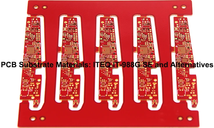
Rogers TMM4 PCB Material – A High-Frequency Performance Overview
The Rogers TMM4 PCB material has emerged as a prominent solution for applications requiring precise high-frequency performance. Designed for industries such as aerospace, medical devices, and telecommunications, it meets the demands of RF and microwave circuits by offering outstanding signal clarity, minimal signal loss, and thermal stability under a variety of conditions.
For high-frequency designs, the performance of PCB materials like FR4 or PTFE often fails to meet the stringent demands of modern systems. Rogers TMM4, however, delivers reliable signal transmission across a broad frequency range, handling complex designs where performance consistency is a necessity.
Exploring Rogers TMM4 further, we can examine its core composition, dielectric properties, and how it compares to other materials commonly used in high-frequency applications.
The Core Composition and Structure of Rogers TMM4
The material’s structure combines a unique ceramic-polymer composite that enhances both mechanical strength and thermal stability. The inclusion of ceramic fillers strengthens the laminate, while the polymer matrix ensures ease of processing during manufacturing.
Rogers TMM4 features uniform dielectric properties, with a dielectric constant (Dk) that remains consistent across a wide frequency range. This stability ensures predictable signal transmission. In high-frequency circuits, even small variations in Dk can lead to signal distortion or phase shift, making TMM4 a reliable choice for minimizing these issues.
Additionally, Rogers TMM4 boasts a low coefficient of thermal expansion (CTE), which reduces the risk of warping or deformation during thermal cycling. This characteristic makes it well-suited for environments that experience fluctuating temperatures, such as aerospace and medical device applications.
Dielectric Constant (Dk) and Loss Tangent (Df) of Rogers TMM4
Two properties to assess in RF materials are dielectric constant (Dk) and loss tangent (Df). These factors impact the material’s signal transmission efficiency and its ability to maintain signal integrity across frequencies.
Dielectric Constant (Dk)-
The dielectric constant reflects a material’s ability to store electrical energy in an electric field. For Rogers TMM4, the Dk typically ranges from 4.5 to 4.7, remaining stable across a wide frequency range. This stability helps keep signal phase and timing consistent in high-frequency applications.
Loss Tangent (Df)-
Loss tangent (Df) measures the energy loss as the signal travels through the material. Rogers TMM4 features a low Df value, typically around 0.002. This translates into minimal energy loss and efficient signal propagation without excessive heat generation, a core factor in high-frequency applications where heat can cause degradation of both signal quality and performance.
Rogers TMM4 vs. Conventional RF PCB Materials – Why It Stands Out?
Comparing Rogers TMM4 to more common RF PCB materials reveals several advantages, particularly for microwave and RF applications. PTFE, FR4, and similar materials are often insufficient for designs that require consistent high-frequency performance.
1. Performance at High Frequencies-
Rogers TMM4 maintains excellent signal integrity and low loss at microwave frequencies. Unlike FR4, which exhibits increased signal loss and dielectric instability at higher frequencies, Rogers TMM4 offers better consistency and minimal interference over a wide frequency spectrum.
2. Durability and Thermal Stability-
The material’s low CTE ensures its stability under fluctuating environmental conditions. While FR4 is prone to thermal distortion, Rogers TMM4 resists warping or dimensional changes, which could interfere with the PCB’s electrical performance in systems that are exposed to extreme temperatures.
3. Processing Ease-
Compared to PTFE and ceramic-based materials, Rogers TMM4 is easier to process. This material is highly machinable, laminable, and compatible with standard PCB manufacturing techniques, making it a more cost-effective solution for high-performance microwave circuits.
Electrical and Mechanical Properties of Rogers TMM4 for RF & Microwave Circuits
In the world of high-frequency circuit design, the materials chosen for PCBs significantly affect the performance of the final product. As RF (radio frequency) and microwave circuits push the boundaries of speed and efficiency, the demands placed on PCB materials become more complex. Among the various options, Rogers TMM4 is often selected for its strong electrical performance and mechanical stability in these challenging applications.
Rogers TMM4 is specifically engineered to provide an optimal balance between dielectric properties and mechanical reliability. These characteristics are essential when dealing with high-frequency signals where small changes in the material’s performance can lead to signal degradation or system malfunction. Understanding the material’s dielectric stability, thermal expansion behavior, and moisture absorption characteristics helps ensure that the circuit will perform consistently over time.
The following sections delve deeper into the specific electrical and mechanical properties of Rogers TMM4, demonstrating how these features contribute to its effectiveness in RF and microwave circuit applications.
Rogers TMM4 Dielectric Stability and Signal Integrity in High-Frequency PCBs
A major concern in high-frequency PCB design is maintaining signal integrity. Rogers TMM4 excels in this area by offering a dielectric constant (Dk) that remains stable across a wide range of frequencies. With a Dk value of approximately 4.50 ± 0.045, this material ensures that the signal transmission is stable and predictable, even at very high frequencies.
In high-frequency applications like microwave circuits, 5G systems, and radar technology, fluctuations in dielectric constant can cause signal distortion, phase shift, and timing errors that degrade performance. Rogers TMM4, with its exceptional dielectric stability, minimizes these issues, making it a suitable choice for designs that demand precision. It delivers predictable and consistent performance in systems that rely on tight timing and high-speed data transmission, such as telecommunications and aerospace systems.
Moreover, Rogers TMM4’s low loss tangent (Df) contributes to improved signal integrity by minimizing energy loss during transmission. The material’s low Df ensures that less power is dissipated as heat, allowing the circuit to operate more efficiently, even in the most demanding applications.
Rogers TMM4 Dielectric Stability and Signal Integrity – Key Data-
| Property | Value | Impact on Performance |
| Dielectric Constant (Dk) | 4.50 ± 0.045 | Stable signal transmission across frequencies. |
| Loss Tangent (Df) | 0.0020 | Minimizes energy dissipation, improving efficiency. |
| Signal Integrity | High | Maintains phase accuracy and system stability. |
By maintaining these properties, Rogers TMM4 ensures predictable performance in systems that demand tight timing and high-speed data transmission, such as telecommunications and aerospace systems.
Thermal Expansion Coefficient (CTE) and Rogers TMM4 Reliability in Harsh Environments
Thermal expansion is a main factor when designing PCBs that will be exposed to extreme temperature variations, such as those in aerospace, automotive, or defense applications. Materials with inconsistent thermal stability may expand or contract at different rates, leading to warping or misalignment of components on the board, which can impact the performance of the circuit.
Rogers TMM4 is designed with a low coefficient of thermal expansion (CTE), meaning it experiences minimal expansion or contraction when temperatures change. This is especially beneficial for microwave circuits, where maintaining precise alignment of components is necessary for signal clarity and reliable operation. The material’s low CTE helps reduce mechanical stress on the components, ensuring the circuit maintains its integrity and performs effectively, even in environments with temperature variations.
Thermal Expansion Coefficient (CTE) of Rogers TMM4-
| Property | Value | Impact on Performance |
| Coefficient of Thermal Expansion (CTE) | < 15 ppm/°C | Ensures dimensional stability even with temperature fluctuations. |
| Thermal Conductivity | 0.45 W/m·K | Helps prevent overheating, improving long-term reliability. |
For applications that involve high power or exposure to extreme temperatures, Rogers TMM4 maintains its dimensional stability, preventing issues like delamination or misalignment of the circuit.
Moisture Absorption, Surface Resistivity, and Long-Term Performance of Rogers TMM4
Moisture absorption is a frequent concern in high-frequency PCBs, especially in environments with fluctuating humidity or exposure to water. Rogers TMM4 is designed to minimize moisture absorption, which helps maintain long-term electrical performance. Excess moisture absorption can cause higher dielectric losses, signal degradation, and potential circuit failure. With its low moisture absorption rate, Rogers TMM4 retains its dielectric properties over time, ensuring stable performance even in humid conditions.
In addition, surface resistivity is an influential factor in high-frequency PCB performance. Rogers TMM4’s surface resistivity is well-suited for high-speed applications, preventing electrical leakage and maintaining signal integrity throughout the PCB. This makes it a dependable choice for medical devices, telecommunications systems, and defense electronics, where stable and consistent signal transmission is required.
Moisture Absorption & Surface Resistivity – Key Data-
| Property | Value | Impact on Performance |
| Moisture Absorption | < 0.03% | Prevents dielectric degradation in humid conditions. |
| Surface Resistivity | > 10^14 ohms/sq | Prevents electrical leakage and ensures signal integrity. |
| Long-Term Reliability | High | Ensures durable and stable performance in demanding environments. |
The long-term performance of Rogers TMM4 is an attractive feature for industries requiring durable, high-quality microwave circuits. The material’s resistance to moisture, chemical degradation, and environmental wear ensures that RF and microwave circuits using Rogers TMM4 will perform reliably throughout their operational lifetime, even in harsh or fluctuating environmental conditions.
Rogers TMM4 PCB Manufacturing – Best Practices for Precision Engineering
The design and production of Rogers TMM4 PCBs for RF and microwave applications demands precision and attention to detail across every step of the manufacturing process. From etching to drilling and plating, each phase contributes to the overall performance and reliability of the end product. The correct approach is necessary to preserve the material’s dielectric properties, thermal stability, and mechanical strength.
As Rogers TMM4 offers superior signal integrity and thermal performance, PCB manufacturers must follow specific procedures to prevent issues during fabrication. The following sections cover the core processes that ensure Rogers TMM4 meets the expectations for high-frequency applications.
Rogers TMM4 PCB Fabrication Techniques – Etching, Drilling & Plating Considerations
The fabrication of Rogers TMM4 PCBs requires detailed methods to ensure that the material maintains its performance during etching, drilling, and plating. Each of these techniques has specific considerations to avoid compromising the material’s characteristics, such as dielectric constant and signal loss.
1.Etching: Etching in Rogers TMM4 PCBs must be carefully controlled to avoid damaging the substrate or affecting the signal path. Standard etching methods can be applied, but modifications might be necessary to maintain the integrity of high-frequency traces. Improper etching could lead to defects like signal distortion.
2.Drilling: Precision is necessary when drilling vias in Rogers TMM4. The material’s low CTE (Coefficient of Thermal Expansion) means drilling parameters must be adjusted to prevent cracking or damage. The right equipment and techniques will ensure clean holes without affecting signal transmission.
3.Plating: The plating process is necessary for ensuring conductivity in vias and traces. Consistent plating thickness helps maintain signal strength and quality. Rogers TMM4 requires careful management of plating processes to prevent copper delamination or uneven surfaces, which could lead to reliability issues.
Multilayer PCB Stacking with Rogers TMM4 – Ensuring PTH & Laminate Integrity
Multilayer PCBs are commonly used for compact high-frequency circuit designs. When stacking multiple layers of Rogers TMM4, it’s necessary to maintain the integrity of the layers and plated through holes (PTH) to ensure reliable performance.
1.Layer Bonding: When stacking multilayer PCBs, the layers must bond properly to avoid issues like delamination. Rogers TMM4 is designed for reliable layer bonding in high-frequency environments. Proper handling of temperature and pressure during lamination is required to ensure that all layers adhere without compromising performance.
2.PTH Integrity:PTH quality affects the creation of multilayer PCBs. Misalignment or contamination during drilling and plating can lead to open circuits and shorts. Ensuring clean, uniform holes and well-coated walls helps preserve signal transmission.
3.Laminate Integrity: The adhesion between the copper layers and Rogers TMM4 must be managed throughout the multilayer stacking process. Special care is needed when preparing the surface of Rogers TMM4 for proper copper bonding. Any weaknesses at this stage could lead to issues in the final product.
Adhesion, Copper Peel Strength, and Processing of Rogers TMM4 in PCB Manufacturing
Proper adhesion and copper peel strength are main aspects of the Rogers TMM4 PCB manufacturing process. The bond between the copper layers and Rogers TMM4 determines how well the PCB will perform under stress and over time.
1.Adhesion: Achieving strong adhesion between Rogers TMM4 and copper is necessary to prevent delamination during the PCB’s service life. Surface treatments like plasma cleaning or mechanical abrasion are often applied to enhance adhesion before copper plating.
2.Copper Peel Strength: The peel strength of the copper traces in Rogers TMM4 must be high enough to withstand mechanical forces during thermal cycling and assembly. Testing the copper peel strength ensures that the traces won’t separate from the substrate under stress, guaranteeing the longevity and reliability of the PCB.
3.Processing Considerations: The processing conditions for Rogers TMM4 differ from those for traditional PCB materials. Careful temperature and pressure control are necessary during lamination and copper plating. Any variation in these parameters can affect the adhesion strength and result in defective PCBs.
Common Engineering Challenges and How Rogers TMM4 Solves Them?
Designing RF and microwave PCBs comes with its fair share of hurdles. Engineers dealing with high-frequency circuits often run into issues such as signal degradation, dielectric inconsistencies, mechanical deformation, and manufacturing defects. These challenges can lead to performance fluctuations, increased failure rates, and excessive production costs.
Rogers TMM4, a ceramic-filled PTFE laminate, offers characteristics that help navigate these difficulties. Its well-controlled dielectric properties, thermal stability, and mechanical resilience make it a practical choice for applications in radar systems, satellite communications, and medical imaging equipment. Below, we break down three major concerns engineers face and how this material provides a solution.
Managing Signal Loss & Dielectric Variability in RF PCB Design
One of the most pressing concerns in RF circuit design is preserving signal clarity across a wide frequency range. Many standard PCB materials show variations in dielectric constant (Dk) and loss tangent (Df), leading to unpredictable impedance shifts, attenuation, and phase distortion.
How Rogers TMM4 Addresses This Issue-
●Consistent Dielectric Properties: With a well-controlled Dk, Rogers TMM4 provides predictable impedance performance, helping our engineers maintain phase accuracy in applications like power amplifiers and filter networks.
●Low Signal Loss: The Df of Rogers TMM4 is significantly lower than many conventional substrates, reducing energy dissipation and preserving signal strength, which is a major advantage in millimeter-wave designs.
●Reduced Conductor Losses: Compatible with low-profile copper foils, this laminate minimizes skin effect losses, which can become a concern at higher frequencies.
Dielectric Performance Comparison-
| Property | Rogers TMM4 | Standard FR-4 | PTFE-Based Laminates |
| Dielectric Constant (Dk) @ 10 GHz | 4.5 ± 0.045 | 4.3 – 4.8 | 2.1 – 2.6 |
| Dissipation Factor (Df) @ 10 GHz | 0.002 | 0.015 – 0.020 | 0.0009 – 0.002 |
| Frequency Stability | Highly stable | Variable | Stable but requires special processing |
Handling PCB Warpage & Delamination in High-Reliability Applications
PCB warpage and layer delamination are frequent concerns, especially when materials undergo high-temperature processing, repeated thermal cycling, or exposure to harsh environments. Dimensional instability can cause misalignment of multilayer stack-ups, via failures, and mechanical stress fractures.
What Sets Rogers TMM4 Apart?
●Low Coefficient of Thermal Expansion (CTE): Its CTE is closely matched to copper, reducing the chance of stress-induced fractures in plated-through holes (PTHs) and interconnect failures.
●Superior Dimensional Stability: Unlike many traditional laminates, Rogers TMM4 maintains mechanical uniformity, making it a strong choice for RF systems.
●High-Strength Laminate Bonding: The ceramic-filled structure resists delamination, even under moisture exposure and high-power dissipation scenarios.
Thermal Expansion & Stability Metrics-
| Property | Rogers TMM4 | Standard FR-4 | PTFE-Based Laminates |
| CTE (X/Y axis) (ppm/°C) | 11 – 13 | 14 – 18 | 17 – 25 |
| CTE (Z-axis) (ppm/°C) | 20 – 25 | 45 – 55 | 80 – 100 |
| Moisture Absorption (%) | 0.02% | 0.10% – 0.30% | 0.01% – 0.10% |
For engineers designing high-power RF circuits or PCBs exposed to extreme temperatures, Rogers TMM4 reduces the risk of dimensional instability and costly defects.
Improving Manufacturing Yield and Reliability – A Process Engineer’s Perspective
Even with top-tier materials, fabrication techniques can make or break a PCB’s performance. Issues like poorly drilled vias, etching inconsistencies, and adhesion failures can lead to lower production yields and increased costs.
Why Rogers TMM4 Supports a Smooth Manufacturing Process-
●Optimized Drilling & PTH Formation: The ceramic content provides a more stable drilling response, resulting in cleaner hole walls and reduced resin smear, improving PTH reliability.
●Strong Copper Adhesion: Unlike many PTFE-based laminates, Rogers TMM4 offers superior copper peel strength, reducing risks of foil delamination during etching and soldering.
●Consistent Processing: Compatible with standard PCB etching methods, this laminate minimizes etch-back issues, making it easier to achieve fine-line geometries in RF designs.
Manufacturing Process Benefits-
| Fabrication Factor | Rogers TMM4 | PTFE-Based Laminates |
| Drill Wear Rate | Moderate | High (requires specialized drills) |
| Copper Peel Strength (lbs/in) | >8.0 | <5.0 |
| Plasma Treatment Required? | No | Yes |
| Multilayer Registration Accuracy | Very High | Moderate |
High-Power RF and Microwave Applications of Rogers TMM4 PCBs
Advancements in RF and microwave technology are pushing industries toward higher frequency operations. However, maintaining circuit performance in complex electromagnetic environments requires a PCB substrate with stable electrical properties and robust structural integrity. Rogers TMM4 has become a good choice in 5G communication, satellite systems, radar technology, and medical imaging due to its low-loss characteristics, excellent thermal stability, and mechanical strength.
Let’s dive into how Rogers TMM4 supports these high-end applications.
Rogers TMM4 in 5G Base Stations, Satellite Communications & RF Power Amplifiers
5G infrastructure, satellite communication, and RF power amplifiers demand PCB materials with consistent signal transmission and thermal reliability. As the industry shifts toward millimeter-wave and high-frequency bands, controlling signal integrity, impedance matching, and power efficiency has become a primary challenge for us.
Why Rogers TMM4 Stands Out in These Applications-
●Stable Dielectric Constant (Dk) – Maintains phase consistency, preventing signal distortion in massive MIMO 5G and satellite communication systems.
●Low Loss Tangent (Df) – Reduces attenuation, ensuring RF power amplifiers operate efficiently under high-power loads.
●Superior Thermal Performance – Manages heat dissipation effectively, preventing thermal drift that can impact high-frequency performance.
Aerospace & Military Radar Systems Using Rogers TMM4 for High-Frequency Stability
Modern radar technology relies on precise RF signal transmission for target detection, tracking, and data communication. Military and aerospace applications, including airborne radar, missile guidance, and UAV communication systems, require PCB materials that offer dimensional stability, temperature resistance, and signal consistency under extreme conditions.
How Rogers TMM4 Meets Radar System Demands-
●Low Coefficient of Thermal Expansion (CTE) – Maintains electrical and mechanical properties across aerospace, satellite, and tactical radar applications.
●Minimal Dielectric Loss – Allows signals to travel longer distances without distortion, ensuring accurate radar imaging and long-range detection.
●Environmental Resilience – Performs reliably in high-humidity, high-radiation, and extreme temperature conditions, meeting military-grade standards.
Rogers TMM4 in Medical Imaging, MRI, and High-Precision Diagnostic Equipment
In MRI, CT scans, ultrasound diagnostics, and RF therapy equipment, PCBs influence signal accuracy and image quality. Any signal interference can affect a medical diagnosis, so selecting the right PCB material is a major consideration in healthcare electronics.
Why Medical Equipment Manufacturers Choose Rogers TMM4-
●Reduced Electromagnetic Interference (EMI) – Minimizes cross-talk and parasitic effects, leading to sharper MRI and CT scan images.
●High Moisture Resistance – Ensures stability in humid environments and high-temperature sterilization processes, extending device longevity.
●Consistent Performance Over Time – Withstands high-frequency pulses and high-power RF signals without degradation, maintaining signal clarity in diagnostic imaging.
In medical electronics, precision is everything—Rogers TMM4 helps designers create more accurate and reliable diagnostic systems.
Impedance Control and RF Performance Optimization with Rogers TMM4
Designing high-frequency circuits requires precise impedance management and signal consistency. Rogers TMM4 provides an advanced dielectric substrate that enables stable signal transmission, making it well-suited for RF, microwave, and millimeter-wave applications.
To achieve reliable performance in radar systems, 5G networks, aerospace electronics, and high-speed data communication, we must carefully consider transmission line structures, minimize electromagnetic interference (EMI), and optimize PCB stack-ups.
Let’s dive into some of the best approaches for refining RF circuit performance with Rogers TMM4.
Transmission Line Design for Rogers TMM4 – Microstrip vs. Stripline Configurations
The way transmission lines are structured affects impedance consistency and signal flow. Microstrip and stripline designs are widely used for high-frequency applications, each with its own set of advantages.
Microstrip Transmission Lines-
A microstrip consists of a signal trace placed on the top layer of the PCB with a ground plane beneath it, separated by Rogers TMM4’s dielectric material. This setup is commonly used due to its straightforward manufacturing process and predictable impedance behavior.
●More efficient fabrication compared to stripline
●Higher radiation loss at extremely high frequencies
●Simple impedance tuning through trace width adjustments
Stripline Transmission Lines-
A stripline places the signal conductor between two ground planes, entirely embedded in the Rogers TMM4 dielectric material. This structure provides greater protection from outside interference and is frequently used in multi-layer RF PCB designs.
●Better shielding from external noise
●Stable impedance across different operating temperatures
●Requires precise layer stacking techniques to avoid inconsistencies
Microstrip vs. Stripline Comparison-
| Feature | Microstrip | Stripline |
| Impedance Control | Good, simple adjustment via trace width | Very stable, needs precise design |
| Noise Shielding | Moderate, less isolation | Excellent, fully enclosed in dielectric |
| Frequency Range | Up to 40 GHz (with considerations) | Up to 50 GHz and beyond |
| Ease of Fabrication | Simpler, cost-effective | More complex, higher manufacturing cost |
Choosing between microstrip and stripline depends on design complexity, frequency range, and EMI requirements.
Controlling EMI & Crosstalk in Rogers TMM4 High-Frequency PCB Designs
Electromagnetic interference (EMI) and crosstalk can cause unwanted signal distortion, impacting RF circuit reliability. As frequencies rise, even small layout miscalculations can introduce performance issues, making noise reduction a major focus when designing with Rogers TMM4 substrates.
Methods to Reduce EMI in Rogers TMM4 PCBs-
●Optimized Grounding Strategy – Well-structured ground planes with low-inductance return paths help reduce noise.
●Minimizing Parasitic Capacitance – Keeping adequate trace spacing and reducing unnecessary vias prevents unwanted coupling.
●Shielding & Isolation – Using RF shielding techniques and separating high-frequency and low-frequency signals prevents interference.
Crosstalk, which occurs due to electromagnetic coupling between adjacent traces, can be controlled by:
●Maintaining sufficient spacing between signal traces
●Using differential pairs for noise cancellation
●Fine-tuning PCB stack-up to keep impedance in check
EMI & Crosstalk Reduction Techniques for Rogers TMM4-
| Technique | Effectiveness | Implementation Notes |
| Ground Plane Design | High | Low-inductance, close to signal layers. |
| Trace Spacing & Via Minimization | Medium | Use controlled spacing for signal isolation. |
| Shielding & Isolation | Very High | Effective for complex RF systems needing minimal noise. |
| Differential Pairs | Very High | Reduces crosstalk by balancing the signal path. |
These methods help ensure that Rogers TMM4-based designs stay stable and reliable even in noisy environments with heavy signal traffic.
Best Practices for Optimizing Rogers TMM4 PCB Stack-Up for RF Signal Integrity
PCB stack-up design directly affects signal transmission, power distribution, and thermal behavior. Rogers TMM4’s dielectric properties enable us to develop layered PCB structures that reduce losses and improve signal propagation.
Key Considerations for Rogers TMM4 Stack-Up Design-
●Layer arrangement – Placing RF signal layers close to ground planes helps maintain impedance accuracy.
●Dielectric thickness selection – Choosing the right TMM4 core thickness prevents signal loss and reflection issues.
●Copper weight optimization – Thin copper layers reduce skin effect losses, improving RF transmission.
PCB Stack-Up Design Considerations for Rogers TMM4-
| Design Factor | Recommended Value | Impact on RF Performance |
| Layer Arrangement | RF signal near ground | Maintains impedance and reduces reflection. |
| Dielectric Thickness | 20 mils – 50 mils | Prevents signal degradation due to excessive loss. |
| Copper Weight (oz/ft²) | 1oz – 2oz | Reduces skin effect, improves transmission. |
| Stack-Up Configuration | Use of multi-layer | Maintains layer uniformity for consistent performance. |
A well-planned stack-up with Rogers TMM4 helps maintain signal integrity, reduce losses, and prevent signal distortion.
Rogers TMM4 vs. PTFE-Based Laminates – Which is Better for RF & Microwave PCBs?
Selecting the right PCB material for RF and microwave applications requires careful evaluation of electrical properties, processing compatibility, and cost-effectiveness. Rogers TMM4 and PTFE-based laminates are both widely used, but their differences impact everything from signal performance to manufacturing efficiency.
Understanding how these materials behave in real-world applications allows for well-informed decisions when developing wireless communication systems, radar equipment, satellite electronics, and high-power RF circuits.
Comparing Rogers TMM4 with PTFE – Electrical Performance & Dielectric Loss
For RF engineers, material selection often starts with dielectric properties and how they affect signal transmission. Both Rogers TMM4 and PTFE laminates offer low dielectric loss, but they differ in how they handle frequency stability, power efficiency, and long-term reliability.
Dielectric Constant (Dk) and Consistency-
●Rogers TMM4 provides a stable dielectric constant (Dk) across various frequencies, allowing for predictable impedance control.
●PTFE laminates are known for low dielectric loss, but their glass reinforcement can cause variations in dielectric properties, affecting consistency.
Loss Tangent and Signal Transmission Efficiency-
●Rogers TMM4 is designed to minimize energy loss, reducing signal degradation over long distances.
●PTFE materials exhibit slightly lower loss, but fabrication complexities and structural inconsistencies can introduce unwanted variables in signal performance.
Thermal Stability and Power Handling-
In high-power applications, materials must handle heat dissipation efficiently.
●Rogers TMM4’s ceramic-filled thermoset composition enhances thermal conductivity while maintaining a low coefficient of thermal expansion (CTE).
●PTFE-based laminates, while effective in RF applications, tend to have higher expansion rates, which may require additional design considerations.
Processing and Manufacturability – Why Rogers TMM4 is Easier to Work With?
Beyond electrical performance, fabrication challenges can determine how smoothly a material integrates into mass production workflows. Here’s how Rogers TMM4 and PTFE laminates compare in real-world manufacturing:
Drilling & Routing-
●Rogers TMM4 can be machined with conventional PCB fabrication techniques, allowing for clean hole drilling and precise routing.
●PTFE-based materials require specialized drilling methods and often demand plasma treatment to prepare hole walls for plating.
Copper Adhesion & Plating Reliability-
●Rogers TMM4’s thermoset resin system enhances copper adhesion, reducing the risk of delamination during processing.
●PTFE laminates, on the other hand, often require chemical surface preparation or roughening treatments before metallization.
Multilayer Stacking & Alignment Precision-
●Rogers TMM4’s low CTE minimizes dimensional shifts, making it more predictable in multilayer constructions.
●PTFE-based laminates tend to expand and contract during processing, leading to registration challenges in high-layer-count designs.
Cost vs. Performance – When to Choose Rogers TMM4 Over PTFE PCB Materials
Material selection isn’t just about performance metrics—it’s about finding the best balance between cost, processing effort, and long-term durability.
Fabrication Costs & Processing Considerations-
●Rogers TMM4 requires fewer specialized fabrication steps, reducing overall production time and costs.
●PTFE-based laminates can have a lower initial material cost, but their processing complexities often lead to higher total expenses.
Application-Specific Considerations-
●For high-frequency applications requiring precise impedance control, Rogers TMM4 provides consistent results without extra processing steps.
●PTFE materials may be preferable in applications demanding ultra-low loss, but their handling challenges can lead to increased production costs.
So, when does Rogers TMM4 make the most sense over PTFE?
●When fabrication simplicity and high yield rates are priorities.
●When thermal expansion control is needed for multilayer PCB designs.
●When a balance of signal performance and processing efficiency is required.
Rogers TMM4 vs. Other High-Frequency PCB Materials
Selecting the right high-frequency PCB material is like choosing the right tool for a precision job—cutting corners can lead to performance hiccups, manufacturing headaches, and long-term reliability concerns. Rogers TMM4 has built a solid reputation for delivering stability and low-loss performance in RF and microwave applications. But how does it compare to other high-frequency PCB materials? Let’s break it down and see what sets these materials apart.
From dielectric properties and thermal expansion to cost and availability, different materials cater to different design needs. Some options provide lower costs, while others focus on flexibility or ultra-low dielectric loss. The following sections take a closer look at how Rogers TMM4 measures up against other widely used high-frequency substrates.
Rogers TMM4 – High-Frequency Performance with Stability
Rogers TMM4 is engineered for applications that require a balance of electrical and mechanical reliability. Its ceramic-thermoset polymer composite ensures consistent performance across frequencies and temperature variations. Unlike PTFE-based laminates, TMM4 combines thermoset resin stability with the benefits of ceramic reinforcement, making it a suitable choice for multilayer designs in demanding environments.
| Property | Rogers TMM4 |
| Dielectric Constant (Dk) | 4.5 – 4.7 (stable across frequencies) |
| Dissipation Factor (Df) | 0.0020 – 0.0023 (low loss tangent) |
| Thermal Coefficient of Dk | Low, ensuring minimal signal variation |
| Coefficient of Thermal Expansion (CTE) | Low, improving dimensional stability |
| Moisture Absorption | Very low, preventing performance shifts |
| Mechanical Strength | High, resistant to warping and delamination |
| Cost | Moderate, higher than FR-4 but lower than premium PTFE materials |
Best suited for:
●Radar, satellite, and aerospace systems.
●5G base stations requiring stable dielectric properties.
●High-temperature environments where thermal expansion must remain controlled.
Rogers RO4000 Series – Cost-Effective High-Frequency Performance
Rogers’ RO4000 series is a widely used alternative for RF applications. Unlike TMM4, these laminates rely on hydrocarbon ceramic-filled materials, making them more cost-efficient but slightly less stable over extreme temperature variations.
| Property | RO4350B | RO4003C | RO3003 |
| Dielectric Constant (Dk) | 3.48 | 3.38 | 3.0 |
| Dissipation Factor (Df) | 0.0037 | 0.0027 | 0.0013 |
| Thermal Coefficient of Dk | Slightly higher than TMM4 | ||
| Mechanical Stability | Good | Good | Lower than TMM4 |
| Cost | Lower than TMM4 |
Best suited for:
●High-volume production where cost plays a main factor.
●Antenna designs needing lower dielectric constants.
●Lower frequency RF designs that don’t require ceramic-thermoset stability.
DuPont Pyralux – Flexibility for High-Frequency Circuits
For designs requiring flexibility, DuPont Pyralux is a go-to material. Used in flex and rigid-flex circuits, Pyralux laminates provide the adaptability that rigid laminates like TMM4 cannot offer.
| Property | Pyralux AP | Pyralux AC |
| Dielectric Constant (Dk) | 3.4 | 3.2 |
| Dissipation Factor (Df) | 0.0024 | 0.0025 |
| Flexibility | High | High |
| Mechanical Strength | Lower than rigid laminates | |
| Cost | Higher due to processing complexity |
Best suited for:
●Wearable electronics and medical imaging devices.
●RF designs requiring flexible circuits.
●Applications where space constraints demand bendable PCBs.
Isola IS620 – High-Performance for Multilayer RF Circuits
Isola’s IS620 is a PTFE-based laminate designed for high-speed digital and RF applications. It offers exceptional electrical performance but comes at a higher price and requires specialized processing.
| Property | Isola IS620 |
| Dielectric Constant (Dk) | 3.2 |
| Dissipation Factor (Df) | 0.0015 |
| Thermal Stability | Excellent |
| Mechanical Strength | High |
| Cost | Higher than TMM4 |
Best suited for:
●Ultra-high-speed data communication systems.
●High-layer count RF designs where loss minimization is a priority.
●Precision radar and defense electronics.
FAQs About Rogers TMM4
1.Can Rogers TMM4 be used for quick-turn PCB prototyping?
Yes, Rogers TMM4 is compatible with quick-turn manufacturing due to its stable dielectric properties and ease of processing.
2.Does TMM4 require special impedance calculations for Quick Turn PCB designs?
TMM4 has a stable dielectric constant, simplifying impedance calculations compared to PTFE. However, layer stack-up, copper thickness, and trace width must still be carefully considered.
3.How does the cost of TMM4 compare to PTFE-based laminates?
TMM4 is more affordable than high-end PTFE materials and does not require additional surface treatment (such as sodium etching), lowering overall manufacturing expenses in Quick Turn PCB production.
4.Is TMM4 easy to laminate in multi-layer PCB stack-ups?
Yes. Compared to PTFE, TMM4 is easier to laminate, works well with FR-4 or other Rogers materials, and reduces lamination failure rates, improving yield in Quick Turn PCB manufacturing.
Our services
Rogers PCB Laminates & Series