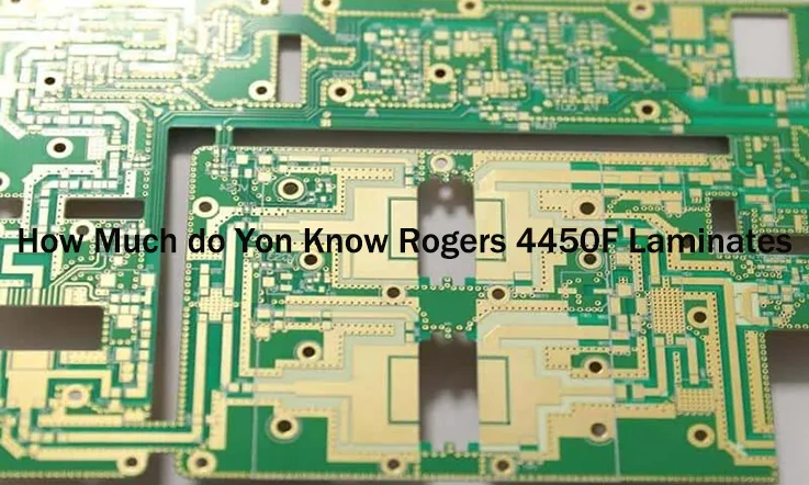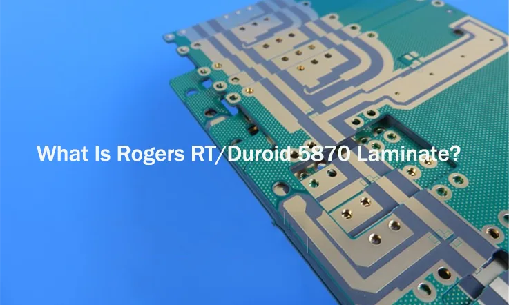
Designing RF, microwave, and millimeter-wave circuits requires materials that maintain signal integrity, low loss, and stable performance across a range of frequencies. Rogers RO5870, a PTFE-based laminate, offers exceptional electrical properties, low dielectric loss, and high thermal stability, making it well-suited for demanding high-frequency applications.
This guide explores manufacturing techniques, compliance standards, reliability testing, and performance considerations when working with RO5870. From controlled impedance design and transmission line optimization to fabrication challenges and environmental resistance, we break down the essential aspects engineers and manufacturers need to consider for efficient PCB production and long-term durability.
Introduction to Rogers RO5870: A Reliable Choice for High-Frequency PCBs
High-frequency PCB design requires materials that provide consistent electrical performance and stable mechanical properties under demanding conditions. Rogers RO5870, a low-loss PTFE-based laminate, meets the needs of RF, microwave, and millimeter-wave applications by offering well-controlled impedance, low dispersion, and high-frequency stability. This material supports the development of phased-array antennas, power amplifiers, satellite transceivers, and millimeter-wave components, making it a widely used option in telecommunication, aerospace, and advanced radar systems.
Electrical and Mechanical Features of Rogers RO5870
Dielectric Characteristics and Frequency Stability-
For circuits operating above 1 GHz, maintaining a stable dielectric constant (Dk) is necessary to avoid phase distortion and signal propagation inconsistencies. RO5870 features a Dk of 2.33, which remains uniform across a broad frequency range. This property helps in designing filters, power dividers, and transmission line networks where precise impedance matching is a priority.
With a dissipation factor (Df) of 0.0012 at 10 GHz, RO5870 minimizes energy loss, making it effective for low-noise amplifiers, RF filters, and high-efficiency antennas. Unlike conventional materials, which tend to attenuate high-frequency signals, RO5870 ensures efficient power transfer, reducing undesired signal loss.
Thermal Expansion and Dimensional Stability-
Temperature variations can cause material expansion and contraction, which may lead to circuit misalignment and performance inconsistencies in high-frequency applications. RO5870 has a low coefficient of thermal expansion (CTE), closely matching that of copper, allowing better reliability in multilayer PCB designs. This feature is particularly helpful in aerospace and defense electronics, where PCBs are exposed to fluctuating environmental conditions.
Furthermore, the reinforced PTFE structure enhances dimensional stability, ensuring that circuit parameters remain consistent over time. Engineers designing phased-array radar systems and high-speed signal processing units benefit from this property, as it allows greater precision in signal transmission and reception.
Copper Adhesion and Etching Capabilities-
Standard PCB laminates sometimes struggle with copper adhesion, leading to etch variations that can affect high-frequency circuit performance. RO5870 supports strong copper bonding, enabling precise thin-line etching down to sub-millimeter widths. This ensures that microstrip and stripline transmission lines maintain their designed impedance, reducing signal reflections and enhancing RF circuit efficiency.
How Rogers RO5870 Compares to Conventional PCB Materials?
Dielectric Performance vs. FR4 and Other Materials-
Standard FR4 laminates exhibit dielectric property variations at higher frequencies, which can introduce signal propagation delays and unexpected impedance shifts. In contrast, RO5870 maintains a stable dielectric profile, making it a better fit for filters, power splitters, and high-frequency antennas that require precise tuning.
Compared to ceramic-filled PTFE laminates, RO5870 offers a more uniform dielectric response, enhancing wideband circuit efficiency. This makes it suitable for broadband impedance-matching networks, couplers, and RF components operating across multiple frequency bands.
Signal Attenuation and Impedance Matching-
Materials with higher loss introduce dielectric heating and unwanted signal reflections, impacting RF link budgets and antenna efficiency. RO5870’s low-loss PTFE composition reduces attenuation, supporting long-distance signal transmission in spaceborne communication systems, avionics, and mmWave automotive radar modules.
Additionally, RO5870 provides predictable Er values, minimizing return loss in high-frequency microstrip and stripline circuits. This enhances signal clarity in multi-layered RF backplanes and interconnects, allowing us to design stable and high-performance RF systems.
Enhancing RF and Microwave Circuits with Rogers RO5870
Millimeter-Wave and 5G Performance Considerations-
5G and millimeter-wave technology demand low-loss substrates to sustain high-data-rate transmissions. RO5870’s ultra-low dissipation factor ensures minimal signal degradation, making it well-suited for 5G beamforming networks, phased arrays, and radar sensors.
Unlike conventional materials, which can struggle with thermal and frequency stability, RO5870 maintains electrical consistency even under high-power RF conditions. This is beneficial for 5G massive MIMO antenna arrays and satellite uplink modules, where maintaining low insertion loss and stable impedance is necessary.
Reliability in Harsh Environments-
Defense and aerospace applications require materials that withstand temperature fluctuations, vibration, and humidity exposure. RO5870 has a moisture absorption rate of just 0.02%, reducing the risk of dielectric property changes in humid or high-altitude environments.
For space-based applications, radiation resistance and long-term dielectric stability are essential. RO5870 has been successfully used in satellite transceivers and deep-space probes, where maintaining signal integrity over long-duration missions is a design consideration.
Manufacturing Compatibility and Fabrication Guidelines-
High-frequency circuit fabrication requires precision etching and via-drilling techniques. RO5870 supports advanced photolithography and laser-drilled vias, allowing fine-pitch interconnects for high-speed RF modules.
Additionally, low-profile copper options reduce conduction losses, making it easier to achieve consistent performance across different production runs. This streamlines high-frequency PCB manufacturing, helping us produce repeatable, high-performance circuits.
Rogers RO5870 vs. Alternative High-Frequency PCB Laminates
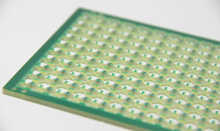
When selecting materials for high-frequency PCB fabrication, human often compare Rogers RO5870 with alternatives like RT/duroid 5880, FR4, RO3003, and Taconic RF-35. Each laminate presents distinct characteristics that influence RF circuit performance, manufacturing processes, and long-term stability. This section provides an in-depth comparison, highlighting how RO5870’s electrical, thermal, and mechanical properties align with different design requirements.
Rogers RO5870 vs. RT/duroid 5880: Material Characteristics and Performance
Both Rogers RO5870 and RT/duroid 5880 utilize PTFE-based substrates for low-loss signal transmission, making them suitable for radar, satellite communication, and phased-array antennas. However, their mechanical structure, dielectric stability, and processing behaviors differ significantly.
Material Property Comparison: RO5870 vs. RT/duroid 5880-
| Property | Rogers RO5870 | Rogers RT/duroid 5880 |
| Dielectric Constant (Dk) @ 10 GHz | 2.33 ± 0.02 | 2.2 ± 0.02 |
| Dissipation Factor (Df) @ 10 GHz | 0.0012 | 0.0009 |
| Moisture Absorption (%) | 0.02 | 0.02 |
| Thermal Expansion Coefficient (CTE, ppm/°C) | 17 (X-axis), 16 (Y-axis) | 22 (X-axis), 21 (Y-axis) |
| Density (g/cm³) | 2.1 | 1.96 |
| Surface Roughness (µm) | 0.6 – 1.2 | 1.0 – 2.0 |
Performance Considerations-
●Dielectric Stability: RO5870’s dielectric constant is tightly controlled, which supports consistent impedance matching across frequency ranges. RT/duroid 5880 has a slightly lower Dk, making it an option for applications prioritizing low-permittivity requirements.
●Signal Loss and Efficiency: Both materials minimize loss, but RT/duroid 5880 has a marginally lower dissipation factor, which can benefit wideband satellite links and spaceborne RF chains.
●Processing Differences: RO5870 contains glass reinforcement, enhancing mechanical integrity while RT/duroid 5880 features a foam-like PTFE structure, which may require careful handling during PCB fabrication.
Rogers RO5870 vs. FR4: Understanding RF Signal Behavior in Different Substrates
FR4 remains a standard choice for digital circuits, but its electrical characteristics become unpredictable at higher frequencies. Rogers RO5870, designed for low-loss, high-frequency applications, delivers a uniform dielectric response that supports RF and microwave signal integrity.
RO5870 vs. FR4: Electrical & Mechanical Properties-
| Property | Rogers RO5870 | Standard FR4 |
| Dielectric Constant (Dk) @ 10 GHz | 2.33 ± 0.02 | 4.5 – 4.8 (varies by frequency) |
| Dissipation Factor (Df) @ 10 GHz | 0.0012 | 0.020 – 0.025 |
| Moisture Absorption (%) | 0.02 | 0.10 – 0.20 |
| CTE (ppm/°C, X-Y plane) | 17 – 16 | 14 – 16 |
| Signal Loss in GHz Range | Minimal | Significant |
Why FR4 Performs Differently in RF Applications-
●Dielectric Constant Variation: FR4’s Dk fluctuates with frequency, leading to impedance drift and increased signal reflection. RO5870 maintains a stable Dk, ensuring predictable RF circuit behavior.
●Loss Characteristics: RO5870 exhibits an ultra-low dissipation factor, allowing RF and microwave signals to propagate with minimal attenuation. FR4, on the other hand, introduces losses that can degrade high-frequency performance.
●Moisture Sensitivity: RO5870 absorbs significantly less moisture, preserving dielectric stability in humid environments. FR4’s moisture absorption leads to dielectric shifts that impact RF circuit accuracy.
For applications exceeding 1 GHz, FR4’s limitations become apparent, making RO5870 the preferred material for RF power amplifiers, phased arrays, and microwave filters.
Comparing Rogers RO5870 with Other PTFE-Based Laminates for Millimeter-Wave Circuit Design
As millimeter-wave technology advances, material selection becomes more data-driven, requiring precise dielectric properties, low signal loss, and stable performance. Alongside RO5870, engineers evaluate laminates like RO3003, RO4350B, and Taconic RF-35, each offering distinct processing and performance characteristics.
Millimeter-Wave Material Comparison: RO5870 vs. Alternatives-
| Property | Rogers RO5870 | Rogers RO3003 | Taconic RF-35 |
| Dielectric Constant (Dk) @ 10 GHz | 2.33 | 3.0 | 3.5 |
| Dissipation Factor (Df) @ 10 GHz | 0.0012 | 0.0013 | 0.0018 |
| Thermal Conductivity (W/m·K) | 0.2 | 0.5 | 0.3 |
| CTE (ppm/°C, Z-axis) | 24 | 25 | 35 |
| Copper Peel Strength (lbs/inch) | 9 | 6 | 8 |
Material Selection Considerations-
●Dielectric Characteristics: RO5870’s low Dk is suited for wideband applications, whereas RO3003 offers slightly higher permittivity, which can be beneficial in miniaturized circuit layouts.
●Thermal Management: RO3003 provides better thermal conductivity, reducing hot spots in power amplifier circuits. RO5870 offers moderate thermal dissipation, making it reliable for steady-state RF applications.
●Processing and Bonding Strength: RO5870 and Taconic RF-35 have higher copper peel strength, ensuring durable etched traces that resist delamination under thermal cycling conditions.
Choosing the right laminate depends on specific RF design constraints, with RO5870 excelling in applications that demand predictable dielectric properties and low loss.
Practical Engineering Guidelines for Designing PCBs with Rogers RO5870
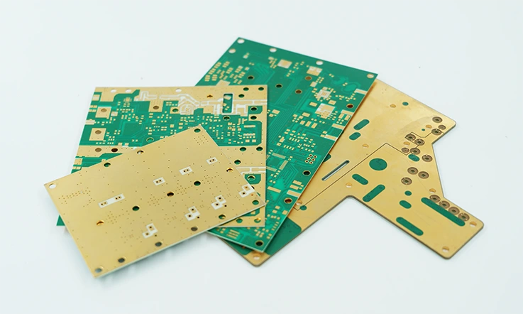
When working with high-frequency PCB laminates, every design choice—from layer stack-up to etching precision—directly impacts circuit behavior. Rogers RO5870, with its low-loss dielectric and stable electrical properties, requires specific fabrication techniques to maximize RF and microwave performance. Whether it’s selecting copper cladding, ensuring impedance consistency, or refining drilling and plating methods, each step demands careful attention to detail.
Rogers RO5870 PCB Layer Stack-Up and Controlling Impedance Across Layers
A well-planned PCB stack-up for Rogers RO5870 ensures consistent impedance matching, minimizes signal distortion, and optimizes power distribution in RF and microwave circuits. Unlike conventional PCB laminates, RO5870’s PTFE-based composition interacts differently with copper foils, prepregs, and core layers, requiring special attention to dielectric spacing and trace geometry.
Stack-Up Guidelines for RO5870 Multilayer PCBs-
| Layer Type | Material Used | Function in RF Design |
| Outer Signal Layers | Copper (½ oz to 2 oz) | RF trace routing and controlled impedance paths |
| Dielectric Core | Rogers RO5870 (2.33 Dk) | Maintains stable signal propagation |
| Prepreg Layers | RO4450F / RO3001 | Adhesion and impedance adjustment |
| Ground/Power Planes | Copper (1 oz to 2 oz) | Provides signal return paths and shielding |
Considerations for RF Circuit Design-
●Trace Width and Spacing: Rogers RO5870 supports fine-line etching, allowing narrower trace widths for higher-frequency applications. Microwave circuits benefit from wider traces to reduce conductor losses.
●Dielectric Layer Thickness: Stack-up thickness affects impedance calculations, so consistent spacing is necessary to prevent variations in signal integrity.
●Ground Plane Positioning: A properly placed ground plane helps maintain low EMI and minimizes parasitic effects in high-speed RF layouts.
By dialing in the right stack-up configuration, we can fine-tune signal propagation, ensuring that RF designs perform as intended without unwanted frequency shifts.
Selecting the Right Copper Cladding for Rogers RO5870 PCB Fabrication
The choice of copper foil influences etching precision, RF performance, and manufacturing yield. Rogers RO5870 supports multiple copper options, each offering different surface roughness characteristics that impact high-frequency signal flow.
Comparison of Copper Cladding Options for RO5870-
| Copper Type | Surface Roughness (µm) | Best Use Cases |
| ED (Electrodeposited) Copper | 1.5 – 3.0 | General-purpose RF and microwave designs |
| Rolled Annealed (RA) Copper | 0.4 – 0.8 | High-speed digital signals, low-loss RF circuits |
| Reverse-Treated (RTF) Copper | 0.6 – 1.2 | Balanced approach for etching and adhesion |
| Low-Profile (LP) Copper | 0.3 – 0.6 | Ultra-low loss applications, mmWave circuits |
Engineering Factors to Consider-
●Skin Effect & Signal Loss: At microwave frequencies, current travels along the outermost layer of copper (skin effect), meaning surface roughness directly affects insertion loss. Lower-profile copper reduces scattering losses in high-speed circuits.
●Etching Precision: Rougher copper foils require adjustments in etch compensation to maintain accurate trace widths. RA and LP copper minimize variations, leading to tighter process control.
●Adhesion & Reliability: While smoother copper improves RF performance, rougher textures like RTF provide better adhesion, reducing the risk of delamination during thermal cycling.
For high-frequency and millimeter-wave designs, choosing the right copper type helps us optimize performance while balancing manufacturing feasibility.
Precision Etching, Plating, and Drilling Techniques for Rogers RO5870 PCBs
Manufacturing RF and microwave PCBs with Rogers RO5870 requires adjustments to etching, plating, and drilling processes. The PTFE-based material structure behaves differently from standard FR4, demanding modified process parameters to maintain tight tolerances and clean vias.
Optimized Manufacturing Parameters for Rogers RO5870-
| Process Step | Recommended Settings for RO5870 |
| Chemical Etching | Ammoniacal etchant, slow rate to minimize undercut |
| Plating Thickness | 20 – 25 µm Cu (via walls) |
| Drilling Speed | 20 – 30 krpm for mechanical drilling |
| Laser Via Drilling | CO2 laser for microvias < 6 mil |
| Surface Finish | ENIG, ENEPIG for corrosion resistance |
Best Practices for Manufacturing RO5870-Based PCBs-
●Etching Control: Standard FR4 etching speeds may cause over-etching on PTFE laminates, so a slower etch rate preserves fine-line accuracy.
●Hole Preparation for Plating: PTFE resins have low adhesion to copper, requiring plasma or sodium treatment before plating to ensure reliable via conductivity.
●Drilling Techniques: Mechanical drilling should use slow feed rates and high RPMs to prevent burr formation and resin smear. For microvias, CO2 laser drilling ensures precise hole formation.
●Surface Finishing: ENIG and ENEPIG finishes improve solderability while maintaining low-contact resistance for high-frequency signals.
By dialing in these process parameters, we can achieve high-yield production while maintaining the electrical integrity of RF circuits built on RO5870.
How Rogers RO5870 Improves Signal Stability in RF and Microwave Circuits?
High-frequency PCB performance depends on precise material selection, optimized transmission line structures, and effective EMI control. Rogers RO5870 offers a well-defined dielectric constant, ultra-low loss, and stable properties, making it a solid choice for RF, microwave, and millimeter-wave circuits. But to fully maximize these advantages, designers must fine-tune impedance, control insertion loss, and minimize crosstalk effectively.
Transmission Line Structures in Rogers RO5870: Microstrip vs. Stripline
Selecting the right transmission line type can make or break the efficiency of an RF circuit. Since Rogers RO5870 is designed for GHz-range applications, understanding the trade-offs between microstrip and stripline ensures that signals travel with minimal interference and distortion.
Comparing Microstrip and Stripline Performance in Rogers RO5870 Designs-
| Feature | Microstrip on RO5870 | Stripline on RO5870 |
| Layer Placement | Routed on outer layers | Embedded within dielectric layers |
| Impedance Control | Requires wider traces for same impedance | More predictable impedance stability |
| Loss Characteristics | Higher radiation losses at high GHz | Lower radiation loss, but higher dielectric loss |
| Manufacturing Complexity | Easier fabrication and tuning | More challenging etching and alignment |
| EMI Considerations | Susceptible to external interference | Naturally shielded between ground planes |
When to Use Each Structure-
●Microstrip layouts are widely applied in wireless systems, phased arrays, and high-frequency amplifiers, where quick adjustments and easy tuning are required.
●Stripline configurations perform well in high-density RF circuits, satellite receivers, and radar processing units, where shielding from external interference is necessary.
For millimeter-wave applications, our engineers often combine both approaches in multilayer stack-ups, optimizing signal routing while controlling unwanted radiation.
Managing Insertion Loss and Phase Distortion in Rogers RO5870 PCBs
At high frequencies, even minor variations in trace geometry, substrate thickness, and copper roughness can lead to unwanted attenuation and phase inconsistencies. Since Rogers RO5870 offers a well-controlled dielectric constant, optimizing circuit layout and material selection ensures signals stay within expected parameters across wide frequency ranges.
Primary Sources of Insertion Loss in Rogers RO5870 Designs-
| Loss Source | Effect on Signal Performance | Mitigation Techniques |
| Dielectric Loss | Causes energy absorption within substrate | Use thinner dielectric layers to reduce loss |
| Conductor Loss | Higher at millimeter-wave frequencies | Select low-profile copper foils |
| Surface Roughness | Creates unwanted signal scattering | Use rolled annealed copper for smoother traces |
| Via-Induced Loss | Can impact signal phase alignment | Use backdrilled or laser vias |
Optimizing Transmission for Better Performance-
●Smooth copper foils like rolled-annealed (RA) or reverse-treated copper (RTF) help maintain consistent signal propagation by reducing skin effect losses.
●Precise stack-up adjustments ensure consistent propagation delays, particularly in multilayer RF circuit boards.
●Minimizing via transitions helps maintain steady impedance matching, avoiding unnecessary signal reflections.
Fine-tuning these aspects prevents excess energy dissipation while keeping signals well-aligned over long distances.
Reducing EMI and Crosstalk in Rogers RO5870 PCB Designs
With GHz-range frequencies packed into small footprints, electromagnetic interference (EMI) and unwanted crosstalk must be tightly controlled. Rogers RO5870 naturally suppresses signal leakage, but further improvements come from careful layout strategies, shielding techniques, and proper grounding.
Common EMI & Crosstalk Challenges in RF Circuitry-
| Issue | Cause | Best Practices to Mitigate |
| Coupling Between Adjacent Traces | High-frequency signals induce parasitic capacitance | Maintain at least 3x trace width spacing |
| Ground Bounce & Signal Reflections | Poor return path continuity | Use solid ground planes under traces |
| Power Supply Noise | Switching regulators introduce harmonics | Use RF-rated bypass capacitors |
| Radiated Emissions from Open Traces | Unshielded signals leak electromagnetic energy | Use stripline structures or shielding enclosures |
Effective Strategies to Control EMI in Rogers RO5870 Designs-
●Routing differential pairs correctly ensures that common-mode noise cancels out naturally, preventing unnecessary interference.
●Via stitching and edge plating help contain stray electromagnetic fields, reducing radiated emissions.
●Placing return ground planes beneath critical traces guarantees a clean return path, preventing ground loops and reflections.
Applying these methods results in cleaner signal paths while keeping unwanted noise out of sensitive circuits.
Advanced Manufacturing Techniques for Rogers RO5870 PCB Fabrication
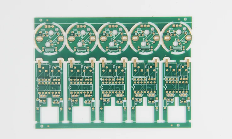
When working with Rogers RO5870, the goal is always to achieve reliable, efficient, and high-performance PCBs that excel in RF and microwave applications. However, its PTFE-based properties introduce unique challenges during the manufacturing process. These challenges can be tackled with specific techniques tailored to Rogers’ materials, ensuring that we can meet the stringent requirements of high-frequency circuit boards.
In this section, we will break down the most effective approaches to fabrication, bonding, and drilling when working with Rogers RO5870, helping us improve their processes for consistency and quality.
PTFE-Based Processing Challenges and Solutions for Rogers RO5870
The use of PTFE (Polytetrafluoroethylene) as the primary dielectric in Rogers RO5870 presents several challenges during the PCB manufacturing process. PTFE materials are known for their excellent low-loss properties and stable performance at high frequencies. However, their tough, non-stick surface makes them tricky to handle during certain stages of PCB fabrication, especially in areas such as lamination and bonding.
Challenges with PTFE Processing-
| Challenge | Solution |
| Poor Adhesion to Copper | Use plasma treatment or adhesion promoters to increase bonding strength |
| Difficulty in Etching Fine Traces | Optimize etching time and use specialized etching chemistry for PTFE materials |
| Non-Uniform Lamination | Control temperature and pressure during the lamination process for consistent bonding |
| Handling High-Temperature Concerns | Use appropriate prepregs and controlled thermal cycles for stable lamination |
Solutions for Efficient PTFE Processing-
●Surface Treatment: Plasma etching is a proven technique for improving adhesion between copper and PTFE-based materials like Rogers RO5870. This ensures better copper bonding and improves the overall longevity and reliability of the final PCB.
●Advanced Etching Technology: To achieve the fine traces required in high-frequency circuits, specialized etching techniques are used to handle the stiff PTFE surface effectively without causing damage to fine line designs.
●Optimized Lamination: Achieving a reliable lamination process depends on precise control of temperature and pressure to create a strong, uniform bond between layers. High-temperature lamination cycles need careful adjustments to prevent material stress and avoid any risk of substrate damage. If the heat and pressure aren’t dialed in just right, you could end up with delamination, voids, or warping—none of which are a good look for high-frequency circuit performance.
Best Practices for Laminating and Bonding Rogers RO5870 PCBs
Lamination of Rogers RO5870 PCBs is a precise process that requires specific attention to temperature, pressure, and material compatibility. When bonding Rogers RO5870 to other materials, prepreg materials and adhesive bonding agents must be selected carefully. Using the right lamination methods ensures the creation of high-quality, long-lasting boards that meet RF and microwave specifications.
Successful Bonding and Lamination Practices-
| Step | Action | Why It Works |
| Preheat PCB Layers | Gradual preheating helps reduce thermal stress and ensures even bonding. | Helps avoid thermal delamination and layer separation. |
| Lamination Process Control | Apply uniform pressure and temperature during the lamination to achieve consistent bond strength. | Ensures uniform lamination and bond integrity throughout. |
| Use of Adhesive Films | Select high-performance prepregs and adhesive films that are specifically designed for Rogers materials. | Supports reliable connections and prevents layer delamination. |
| Curing at Optimal Temperature | Cure the laminate at controlled temperatures using a high-precision oven. | Ensures material integrity and prevents substrate deformation. |
Why These Practices Matter-
Following these practices allows for better adhesion properties and helps the material maintain its low-loss performance and thermal stability. Proper bonding and lamination strengthen the PCB, which is essential in high-performance environments like RF circuit boards and microwave designs.
Drilling, Milling, and Routing Considerations for Rogers RO5870 Circuit Boards
Drilling and milling are essential processes when fabricating PCBs with Rogers RO5870. PTFE materials require specific techniques for precision drilling, proper hole cleaning, and accurate routing. Selecting suitable tools, adjusting spindle speeds, and optimizing feed rates help maintain material integrity and achieve clean, burr-free holes without affecting performance.
Drilling & Milling Challenges-
| Challenge | Solution |
| Hole Deformation | Use high-speed rotary tools with precision for clean, sharp holes |
| Delamination Around Holes | Minimize heat generation during drilling to reduce the risk of layer separation |
| Poor Hole Wall Smoothness | Utilize laser drills and diamond-coated bits for smoother hole walls |
| Milling to High Precision | Employ multi-axis milling machines to achieve tight tolerance specifications |
Best Practices for Drilling and Routing-
●Advanced Drilling Tools: Laser drilling and diamond-coated bits are often used in high-frequency PCB manufacturing to produce precise holes without damaging the PTFE substrate.
●Minimize Heat Generation: Drilling and milling should be done with low feed rates and high spindle speeds to minimize heat and prevent thermal damage to the Rogers RO5870 substrate.
●Routing and Trace Isolation: Automated routing systems with fine tolerances help maintain precise trace isolation, ensuring minimal signal interference in RF designs. Proper calibration and tool selection prevent unintended variations that could affect performance.
Thermal Management and Reliability Testing of Rogers RO5870 PCBs
Managing heat dissipation in high-frequency PCBs like Rogers RO5870 is a major factor in maintaining stable electrical performance over time. Unlike traditional FR4 materials, RO5870’s low dielectric loss and high thermal stability make it a go-to option for RF power applications, but it still requires proper thermal design to handle power dissipation efficiently.
Additionally, reliability testing plays a major role in ensuring long-term durability under real-world operating conditions. Environmental stressors such as moisture absorption, temperature cycling, and mechanical fatigue can impact performance stability over time. In this section, we’ll dive into the best thermal management strategies, reliability testing methods, and environmental resistance properties that impact the practical application of RO5870-based PCBs.
Heat Dissipation Strategies for Rogers RO5870 in RF Power Applications
RF power circuits generate significant heat, and without an effective way to channel it away, performance drift and material degradation can become real headaches. RO5870, with its low dissipation factor (Df) and high thermal conductivity, naturally reduces some of these concerns, but proper design techniques ensure that heat buildup doesn’t turn into a long-term problem.
Optimized Heat Dissipation Techniques for RO5870-Based Designs-
| Heat Dissipation Factor | Optimized Design Approach |
| Copper Thickness Selection | Using 2 oz or thicker copper layers enhances thermal conductivity. |
| Thermal Vias Implementation | Placing plated through-holes (PTHs) in heat-prone areas helps transfer heat away. |
| Heat Sink Attachment | Directly bonding heatsinks or using thermally conductive adhesives prevents hot spots. |
| Metal Core Integration | Hybrid stack-ups with aluminum or copper cores improve thermal handling. |
| Dielectric Heat Transfer Considerations | Selecting prepregs with better thermal properties ensures efficient heat dissipation. |
Why These Methods Work?
●Thicker copper layers increase heat-spreading capability, which is a major win for high-power RF circuits.
●Thermal vias provide an easy escape route for heat traveling through PCB layers.
●Using heatsinks and thermal adhesives keeps sensitive RF components from overheating and shifting electrical properties.
●Hybrid stack-ups with metal cores can absorb and dissipate excess thermal energy, making the overall system more stable.
By combining these strategies, Rogers RO5870 can be effectively used in high-power RF applications without the risk of excessive thermal stress impacting performance.
Long-Term Reliability Testing and Failure Analysis for Rogers RO5870 Boards
Before RO5870-based PCBs make it into high-frequency applications, extensive reliability testing is required to weed out potential failure points. Unlike standard materials, PTFE-based laminates like RO5870 require specific testing to evaluate how they handle temperature extremes, humidity, mechanical stress, and electrical aging.
Common Reliability Tests for Rogers RO5870 PCBs-
| Test Type | Purpose |
| Temperature Cycling (TCT) | Simulates extreme hot/cold cycles to check for delamination and material expansion. |
| High-Power Burn-In | Evaluates long-term stability under full operational load. |
| Moisture Resistance Testing | Measures how much humidity absorption affects dielectric properties. |
| Solder Float and Thermal Shock | Ensures thermal stability during assembly and reflow soldering. |
| Mechanical Stress Analysis | Assesses flexural strength and via integrity after repeated mechanical strain. |
Failure Mechanisms and Preventative Measures-
●Delamination & Cracking: Avoid rapid thermal cycling and use graded heat exposure during assembly to reduce material stress.
●Via Reliability Issues: Use low CTE materials for better via plating adhesion, minimizing barrel cracking risks.
●Dielectric Shifts from Moisture Absorption: Employ low-humidity storage methods and consider protective coatings when designing for harsh environments.
With these reliability tests in place, we can ensure that RO5870-based PCBs hold up under real-world conditions without unexpected performance drift.
Environmental Resistance and Moisture Absorption Properties of Rogers RO5870
High-frequency circuits are highly sensitive to environmental conditions, and RO5870’s PTFE-based structure offers superior resistance to moisture and chemical exposure compared to traditional materials. However, PCB designers still need to account for long-term exposure to humidity, temperature variations, and chemical contaminants.
How Rogers RO5870 Performs Under Environmental Stress-
| Environmental Factor | Impact on RO5870 | Mitigation Strategy |
| Humidity & Moisture | Extremely low moisture absorption (~0.02%) compared to FR4. | Use conformal coatings for extra protection in harsh environments. |
| Temperature Variations | Stable dielectric properties over a wide temperature range. | Optimize stack-up design to minimize CTE mismatches. |
| Chemical Exposure | PTFE structure resists most solvents and acids. | Avoid aggressive cleaning solutions that could degrade copper adhesion. |
| UV & Oxidation Resistance | Does not degrade under prolonged UV exposure. | No special coating required for outdoor applications. |
Why This Matters in Real-World Applications-
●Moisture absorption is practically a non-issue, making RO5870 ideal for humid or tropical environments.
●Its high thermal stability ensures performance doesn’t degrade with temperature swings, reducing the need for excessive compensatory circuit tuning.
●RO5870’s chemical resistance allows it to be used in industrial and aerospace environments without worrying about corrosive exposure breaking down material integrity.
By considering these factors, we can confidently deploy RO5870 PCBs in high-reliability applications where environmental stressors would typically cause degradation in lesser materials.
Compliance, Certifications, and Industry Standards for Rogers RO5870 PCB Materials
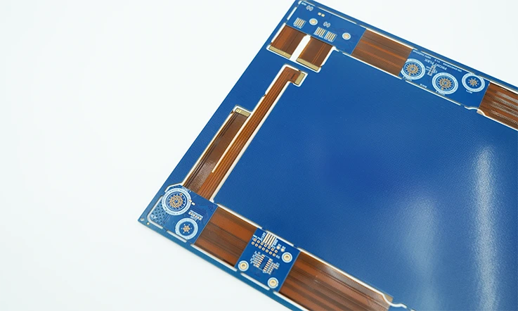
Building RF and microwave circuits with Rogers RO5870 isn’t just about optimizing electrical performance—it also requires meeting strict industry regulations. From military-grade reliability to environmental safety compliance, manufacturers must follow standardized certifications to ensure consistent quality across different applications.
Understanding how RO5870 aligns with IPC, MIL-SPEC, and RoHS certifications helps manufacturers avoid compliance issues while ensuring reliable fabrication processes. Additionally, maintaining tight quality control measures ensures that every fabricated PCB meets high-frequency performance expectations without unexpected setbacks.
Below, we’ll break down the certifications, quality assurance processes, and performance requirements that engineers and manufacturers need to keep in check when working with RO5870-based designs.
IPC, MIL-SPEC, and RoHS Certifications for Rogers RO5870 Laminates
Manufacturing with RO5870 means following a stack of certifications to match industry expectations. The IPC (Institute for Printed Circuits) standards, MIL-SPEC requirements, and RoHS compliance all play a part in ensuring that these laminates can be used in aerospace, military, and commercial applications.
●IPC Standards: RO5870-based PCBs typically follow IPC-6012 for rigid PCB fabrication, while IPC-2221 and IPC-2223 cover design and flex considerations. These standards ensure proper material handling, plating thickness, and via integrity, reducing the risk of delamination or electrical drift.
●MIL-SPEC Compliance: For defense and aerospace applications, RO5870 needs to meet specifications such as MIL-PRF-31032 or MIL-PRF-55110, which dictate strict guidelines on mechanical durability, thermal stability, and signal integrity over extreme conditions.
●RoHS Certification: Unlike traditional PCB materials, RO5870 aligns with RoHS (Restriction of Hazardous Substances) directives, meaning it avoids lead, mercury, and other hazardous compounds, making it viable for environmentally compliant designs.
For manufacturers, keeping up with these standards isn’t just about checking boxes—it ensures that RF and microwave circuits built with RO5870 can be used in applications ranging from military radar systems to commercial wireless networks without compliance headaches.
Quality Control and Inspection Standards for Rogers RO5870 PCB Fabrication
Even the best high-frequency laminates won’t perform as expected if manufacturing inconsistencies creep into the process. Quality control (QC) and inspection protocols play a huge role in ensuring each PCB maintains strict dimensional tolerances, proper etching, and reliable plating adhesion.
Common Quality Control Checks in RO5870 PCB Manufacturing-
1.Automated Optical Inspection (AOI): Detects etching defects, trace width deviations, and solder mask misalignments.
2.X-ray Inspection: Used for examining hidden vias, multilayer alignments, and internal trace defects in RO5870 stack-ups.
3.Dielectric Constant (Dk) Verification: Ensures material consistency since even minor variations in PTFE-based laminates can impact high-frequency performance.
4.Thermal Stress Testing: Simulates real-world heat cycles to check for delamination, via cracking, and material expansion mismatches.
5.Plating Thickness Measurement: Ensures consistent copper thickness for maintaining controlled impedance requirements.
Skipping these QC steps can lead to RF signal degradation, unpredictable impedance mismatches, and even premature board failure. Manufacturers that prioritize thorough inspections can ensure RO5870-based PCBs hold up under demanding RF environments.
Meeting High-Frequency Performance Requirements with Rogers RO5870
Achieving top-tier RF performance with RO5870 isn’t just about picking the right laminate—it requires meticulous design adjustments to maintain low signal loss, predictable impedance, and minimal parasitic effects.
What Engineers Watch for When Designing with RO5870-
●Controlled Impedance Tuning: Since RO5870 operates in GHz frequencies, maintaining tight impedance tolerances ensures consistent signal propagation without phase distortion.
●Low-Loss Transmission Lines: Microstrip and stripline configurations need precise etching tolerances to take full advantage of RO5870’s low dissipation factor (Df).
●Surface Roughness Optimization: Copper surface profiles affect skin depth losses, so selecting rolled copper or low-profile foils helps reduce high-frequency attenuation.
●Moisture & Environmental Stability: RO5870 absorbs significantly less moisture than FR4, ensuring stable dielectric properties even in high-humidity conditions.
●Thermal Expansion Matching: Ensuring CTE compatibility between RO5870 and metal layers prevents delamination and warping issues during high-power operation.
When we dial in these factors, RO5870-based PCBs deliver predictable and stable RF performance, making them reliable choices for applications that demand low signal loss and high-frequency precision.
FAQ & Rogers RO5870
1. How should Rogers RO5870 be stored?
Store in a dry, controlled environment below 30°C with low humidity to prevent moisture absorption.
2. Can Rogers RO5870 be used for multilayer PCBs?
Yes, but requires proper bonding materials and processing techniques for reliable lamination.
3. Does Rogers RO5870 require special drilling techniques?
Yes, PTFE-based laminates need carbide or diamond-coated drills to prevent burring.
4. How does Rogers RO5870 handle high-power applications?
Its low dielectric loss and high thermal conductivity support efficient power handling.
5. What type of plating is recommended for vias in Rogers RO5870 PCBs?
Electroless copper or direct metallization ensures strong adhesion and conductivity.
6. Can Rogers RO5870 be combined with FR4 in hybrid designs?
Yes, but differences in thermal expansion and processing must be carefully managed.
7. Is Rogers RO5870 resistant to harsh chemicals?
Yes, it has strong chemical resistance, but exposure to aggressive solvents should be minimized.
Our services
Rogers PCB Laminates & Series

