As electronic devices continue to advance, the demand rises for printed circuit boards (PCBs) that can support high frequency applications. This has led to increased interest in specialty laminates like Rogers 3010 that are engineered to enable reliable performance at microwave and millimeter-wave frequencies. This article provides a comprehensive overview of Rogers 3010 high frequency PCB substrate material and its use in circuit fabrication.
What Is Rogers 3010 PCB?
Rogers RO3010 laminates are cost-effective products that offer excellent electrical and mechanical stability. These laminates simplify the design of broadband components and enable the use of materials across a wide range of frequencies and applications. They are particularly suitable for circuit miniaturization.
The design of circuit boards using RO3010 laminates focuses on meeting the electrical performance requirements of microwave circuits. These boards are manufactured using high-quality insulating and laminated materials specifically designed for high-frequency applications. They possess exceptional mechanical strength and exhibit high resistance to signal interference.
The RO3010 laminate, a PTFE ceramic-filled composite, can be employed in applications up to 77 GHz. It has a dielectric constant of 11.20 at room temperature, which remains stable up to 40 GHz. Additionally, its dissipation factor at 10 GHz is 0.0022, making it suitable for various applications such as patch antennas, GPS antennas, direct satellite applications, and automotive radars.
Regardless of the chosen dielectric constant, RO3010 laminates exhibit consistent mechanical properties. This characteristic allows designers to develop multi-layer board designs that utilize different dielectric constants for individual layers, without encountering reliability or warpage issues.
The material’s expansion coefficient is similar to that of copper, resulting in excellent dimensional stability and minimal etch shrinkage. RO3010 laminates can be processed into printed circuit boards (PCBs) using standard PTFE circuit processing techniques with minimal modifications.
Therefore, Rogers RO3010 laminates offer competitive pricing, exceptional electrical and mechanical stability, and are ideal for circuit miniaturization. Their high-frequency characteristics make them suitable for a wide range of applications, while their consistent mechanical properties and dimensional stability allow for flexible multi-layer board designs.
Properties and Characteristics of Rogers 3010 PCB
Here are the key properties and characteristics of Rogers 3010 PCB material:
Dielectric Properties
● Dielectric Constant (Dk): 10.2
● Dissipation Factor (Df): 0.0023 max at 10 GHz
● Thermal Coefficient of Dk: 25 ppm/°C
Electrical Properties
● DC Resistance: >1×10^15 Ω-cm
● Volume Resistivity: >1×10^15 Ω-cm
● Surface Resistivity: >1×10^15 Ω
Physical/Mechanical Properties
● Glass Transition Temperature: 330°C
● Thermal Conductivity: 0.6 W/m-K
● Coefficient of Thermal Expansion: 25 ppm/°C
● Tensile Strength: 150 MPa
● Compressive Strength: 450 MPa
Dimensional Properties
● Thickness Range: 0.005″ to 0.065″
● Copper Weight: 1/2 oz or 1 oz
● Feature/Hole Sizes: 4-6 mil
Environmental Properties
● Operating Temp Range: -55°C to 200°C
● Frost/Dew Point: 260°C
● Moisture Absorption: 0.2%
● Flame Rating: UL 94V-0
Application Benefits
● Excellent high frequency performance to 110 GHz
● Extremely low loss enables thin, complex designs
● Dimensionally stable over wide temperature range
● Tighter spacing/features than FR-4 substrates
This makes Rogers 3010 well-suited for dense, multi-layer RF/microwave PCB applications with stringent performance demands.
Data of Rogers RO3010 Base Material
| RO3010 Typical Value | |||||
| Property | RO3010 | Direction | Units | Condition | Test Method |
| Dielectric Constant,εProcess | 10.2±0.05 | Z | 10 GHz/23℃ | IPC-TM-650 2.5.5.5 Clamped Stripline | |
| Dielectric Constant,εDesign | 11.2 | Z | 8GHz to 40 GHz | Differential Phase Length Method | |
| Dissipation Factor,tanδ | 0.0022 | Z | 10 GHz/23℃ | IPC-TM-650 2.5.5.5 | |
| Thermal Coefficient of ε | -395 | Z | ppm/℃ | 10 GHz -50℃to 150℃ | IPC-TM-650 2.5.5.5 |
| Dimensional Stability | 0.35 0.31 | X Y | mm/m | COND A | IPC-TM-650 2.2.4 |
| Volume Resistivity | 105 | MΩ.cm | COND A | IPC 2.5.17.1 | |
| Surface Resistivity | 105 | MΩ | COND A | IPC 2.5.17.1 | |
| Tensile Modulus | 1902 1934 | X Y | MPa | 23℃ | ASTM D 638 |
| Moisture Absorption | 0.05 | % | D48/50 | IPC-TM-650 2.6.2.1 | |
| Specific Heat | 0.8 | j/g/k | Calculated | ||
| Thermal Conductivity | 0.95 | W/M/K | 50℃ | ASTM D 5470 | |
Coefficient of Thermal Expansion (-55 to 288℃) | 13 11 16 | X Y Z | ppm/℃ | 23℃/50% RH | IPC-TM-650 2.4.4.1 |
| Td | 500 | ℃TGA | ASTM D 3850 | ||
| Density | 2.8 | gm/cm3 | 23℃ | ASTM D 792 | |
| Copper Peel Stength | 9.4 | Ib/in. | 1oz,EDC After Solder Float | IPC-TM 2.4.8 | |
| Flammability | V-0 | UL 94 | |||
| Lead-free Process Compatible | Yes | ||||
Design Considerations for Rogers 3010 PCBs
Here are some key considerations for designing PCBs intended for Rogers 3010 circuit materials:
Trace Width/Spacing – Rogers 3010 has a dielectric constant of 10.2, resulting in higher signal propagation speeds compared to FR-4. This allows for tighter trace widths and spacing. Common minimums are 4-5 mil traces with 4-5 mil spacing.
Layer Count – Rogers 3010 is typically used in multilayer boards to take advantage of its RF and high-speed signaling properties. Common configurations are 4, 6, 8 or more layers.
Stackup Design – Proper stackup design is critical for impedance control and layer transitions. Internal power and ground planes provide shielding. Impedance-controlled microstrips or striplines are common.
Drill Diameters – Due to the tighter tolerances, smaller drill bits less than 6 mil are commonly used. Microvias less than 4 mils in diameter are possible.
Surface Finishes – Hasu Plating or ENIG are good choices that won’t degrade the laminate’s RF properties like immersion gold sometimes can.
Impedance Control – Tighter impedance control required, typically ±5% or less. Consider impedance modeling and testing EQ material if possible.
RTD Requirements – Often requires -40 to 125°C temperature cycling for military/aerospace. May need controlled impedance at elevated temps.
RF Signal Routing – Careful routing and isolation of high speed signals from other traces and components. Avoid breaks or stubs in 50 ohm lines.
Stackup/Design Review – Third party RF/high speed design review recommended due to critical timing requirements.
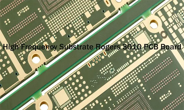
High Frequency Substrate Rogers 3010 PCB Board Fabrication
High-frequency PCBs are a type of circuit board designed to transmit signals with a frequency of 500 MHz or higher. These boards are often used in applications like radio frequency (RF), microwave, and mobile industries.
Rogers Corporation is a prominent manufacturer of high-frequency laminates, and Rogers 3010 is one of their specific materials used for high frequency PCBs. Rogers 3010 has a dielectric constant of 10.2 @ 2.5GHz, which makes it suitable for high-speed designs that require a high dielectric constant.
Here are the steps involved in fabricating a high-frequency substrate Rogers 3010 PCB board:
1. Designing the Circuit: Before fabrication can begin, the circuit needs to be designed using PCB design software. The design should take into account the specific properties of Rogers 3010, including its high dielectric constant.
2. Preparing the Substrate: The Rogers 3010 material is prepared for the fabrication process. This might involve cutting it to the correct size and cleaning it to remove any contaminants.
3. Applying the Circuit Pattern: The circuit pattern is applied to the Rogers 3010 substrate. This is usually done using a process called photolithography, which involves applying a layer of photoresist material, exposing it to ultraviolet light through a mask with the circuit pattern, and then etching away the exposed areas to leave the desired circuit.
4. Drilling Holes: Holes for through-hole components and vias are drilled into the substrate. The locations of these holes are determined by the circuit design.
5. Plating: The circuit and the holes are plated with a thin layer of metal, usually copper. This creates the electrical connections in the circuit.
6. Solder Mask Application: A layer of solder mask is applied to the board. This helps to prevent accidental electrical contact between the circuit and any other metal parts.
7. Component Placement and Soldering: The components are placed on the board and then soldered to the circuit. This can be done manually or with automated machines, depending on the complexity and scale of the fabrication.
8. Testing and Inspection: The finished board is tested to ensure it functions correctly. This might involve visual inspection, electrical testing, or even more specialized tests depending on the application of the board.
Remember, fabricating high-frequency PCBs like a Rogers 3010 board requires special considerations due to the sensitive nature of high-frequency signals. This includes careful control over the dielectric constant and loss factor, as well as the use of specialized materials and processes. It’s important to work with a PCB manufacturer that has experience with high-frequency designs to ensure the best results.
Applications of Roger RO3010 PCB
The RO3010™ laminates series is a high frequency circuit material produced by Rogers Corporation. It has a low dielectric loss, a very stable dielectric constant (εr = 10.2), and a high thermal conductivity. The RO3010 series is commonly utilized in applications requiring high dielectric constant materials.
Here are a few typical applications of RO3010:
Microwave and RF Applications
Due to the RO3010’s high frequency performance and low dielectric loss, it is commonly used in the manufacturing of microwave and RF circuits. The low loss tangent makes it excellent for high frequency signal transmission.
Antenna Systems
RO3010 is often used in antenna systems, especially for millimeter-wave applications. It finds use in various types of antennas like patch antennas, phased array antennas, and slot antennas.
Power Amplifiers
The high thermal conductivity of the RO3010 makes it suitable for applications where heat dissipation is critical, such as power amplifiers. The improved heat transfer helps to maintain the performance of the circuit even at high power levels.
Automotive Radar Systems
The RO3010 is ideal for automotive radar systems. It is used in the design of antennas for radar systems that operate in the 77 GHz and 79 GHz bands, which are increasingly common in advanced driver-assistance systems (ADAS).
Aerospace and Defense Electronics
In aerospace and defense sectors, the RO3010 is used in the production of electronic components and systems that need to operate reliably in extreme conditions. These can include radar systems, communication systems, or electronic countermeasure systems.
Cellular Base Station Antennas
The high dielectric constant of the RO3010 makes it particularly useful for miniaturization. This feature can enable more compact and efficient designs for cellular base station antennas.
Please note that the usage of RO3010 is not limited to the above applications. Its properties make it an attractive choice for a variety of high-frequency, high-power, and high-temperature applications. Always consider the specific requirements of your design when selecting a PCB material.
Advantages and Limitations of Rogers 3010 PCB
Here are some key advantages and limitations of using Rogers 3010 circuit materials for PCBs:
Advantages:
● Excellent RF and high-speed digital performance up to 110 GHz
● Very low loss dielectric enables thinner, more compact designs
● Dimensionally stable over temperature range (-55°C to 200°C)
● Tighter tolerances allow for finer line/spacing and smaller vias
● Consistent dielectric properties provide reliable performance
● Density saves board space in high-frequency applications
Limitations:
● Higher material cost than standard FR-4 circuit boards
● Requires tighter impedance control during fabrication
● More complex multilayer stackups vs FR-4
● Smaller processing margins for drilling and lithography
● Rigid and brittle composition limits cutting and routing
● Special care needed to avoid cracks or delamination
● Requires qualified fabricators experienced with RF materials
● Limited to rigid applications, not suitable for flex circuits
● Environmental restrictions on usage of halogen-free resin
As a result, Rogers 3010 enables advanced high-frequency designs but requires more stringent fabrication. The material and manufacturing costs are higher. It is best suited for applications where performance gains outweigh complexity and expense increases over conventional FR-4.
Conclusion
Rogers 3010 is an excellent choice of PCB substrate material for applications requiring exceptional high-frequency and RF performance, such as 5G, wireless, aerospace and defense systems.
Some key advantages it provides include very low signal loss up to 110 GHz, high dimensional stability over temperature, and the ability to enable more compact designs through tighter trace spacing and smaller via sizes.
However, working with Rogers 3010 also presents some challenges compared to standard FR-4 substrates. Manufacturing requires tighter impedance control and processing tolerances. Stackup designs are more complex with this multilayer material. And the material and fabrication costs are higher.
For applications where the gains in signal integrity and miniaturization outweigh these limitations, Rogers 3010 can deliver best-in-class performance. Suitable end products include mmWave systems, radar, satellite communications, and other use cases pushing the boundaries of frequency and signaling speeds.
With the proper design considerations and an experienced manufacturer, Rogers 3010 PCBs allow the creation of extremely dense, high-speed interconnects ideal for the most advanced aerospace, telecommunications and industrial applications. Its properties make it a goto substrate choice when uncompromising signal quality is required.
In summary, Rogers 3010 is a premium but high-performing material well-suited for cutting-edge, frequency-sensitive PCB designs when used by qualified designers and fabricators. Its advantages in the RF and high-speed domains can significantly improve system capabilities.
Our services
Rogers PCB Laminates & Series

