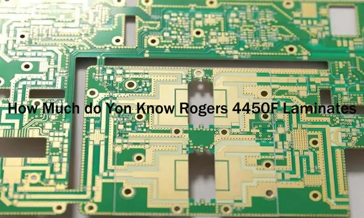
Precision and reliability shape high-frequency PCB design, and Rogers RO4450F PCB is a solid choice for 5G infrastructure, aerospace systems, and RF applications. Featuring low dielectric loss, stable impedance control, and excellent thermal performance, this laminate supports high-speed signal transmission and performs well in demanding environments.
This guide explores material properties, stack-up strategies, thermal management, and supplier selection, providing engineers and procurement specialists with the insights needed to maximize performance and sourcing efficiency.
What is Rogers RO4450F PCB?
Composition, Performance & Features
Rogers RO4450F PCB is a high-performance material used in high-frequency printed circuit board (PCB) design, particularly for applications requiring precise signal transmission and reduced signal loss. It’s commonly employed in sectors like 5G networks, aerospace, medical technology, and radar communications, where maintaining performance under specific conditions is necessary.
Let’s explore the composition, performance characteristics, and features of Rogers RO4450F PCB, so you can understand why it’s a choice for these industries.
Rogers RO4450F PCB Material Composition & Properties
Rogers RO4450F PCB consists of a glass-reinforced epoxy resin matrix combined with ceramic fillers. This blend results in a low dielectric constant (Dk) and a low dissipation factor (Df), helping to preserve signal integrity at high frequencies. It is designed to perform well in high-speed data transmission systems, where reducing signal loss is a main factor.
Here’s a breakdown of Rogers RO4450F properties in comparison with other high-frequency materials:
| Property | Rogers RO4450F | Other High-Frequency Materials (e.g., PTFE) |
| Dielectric Constant (Dk) | 3.52 ± 0.05 | 2.2 – 2.5 (PTFE) |
| Dissipation Factor (Df) | 0.004 | 0.001 – 0.003 (PTFE) |
| Thermal Conductivity | 0.65 W/m·K | 0.25 – 0.30 W/m·K (PTFE) |
| Tensile Strength | 61,000 psi | 50,000 psi (PTFE) |
| Moisture Absorption | 0.10% | 0.03% – 0.08% (PTFE) |
The dielectric constant of Rogers RO4450F is higher than that of PTFE-based materials, making it a good option for applications requiring controlled impedance and minimal signal loss. It also offers improved thermal conductivity, aiding in heat management for high-power applications.
Electrical & Mechanical Performance of Rogers RO4450F PCB
When assessing the performance of Rogers RO4450F PCB, we must consider both its electrical and mechanical properties, which contribute to its suitability in demanding applications.
Electrical Performance-
●Signal Transmission: RO4450F excels at high-frequency signal transmission with minimal attenuation, which ensures that signal quality remains intact even at frequencies up to 40 GHz.
●Dielectric Strength: With a dielectric strength of 50 kV/mm, RO4450F can operate in high-voltage conditions, making it suitable for power-intensive systems such as military communications and medical imaging equipment.
Mechanical Performance-
●Dimensional Stability: The material offers excellent dimensional stability, ensuring it holds its shape under thermal cycling or exposure to high-temperature environments.
●Mechanical Strength: With a tensile strength of 61,000 psi, RO4450F resists mechanical stress and is highly reliable in demanding applications like aerospace and automotive radar systems.
Rogers RO4450F PCB vs. Other High-Frequency Materials
Compared to other materials like PTFE-based laminates, RO4450F offers a better balance between performance and cost-effectiveness. While PTFE is commonly used in RF designs, it is generally less mechanically robust and more expensive than RO4450F.
Here’s a look at how RO4450F fares in comparison:
●PTFE laminates typically excel in low-cost applications but fall short when it comes to mechanical strength and thermal conductivity.
●RO4450F offers better dimensional stability and thermal conductivity, which makes it more reliable in environments where signal stability and thermal management are a priority.
Rogers RO4450F PCB Stack-Up Design
Optimizing High-Frequency PCB Performance
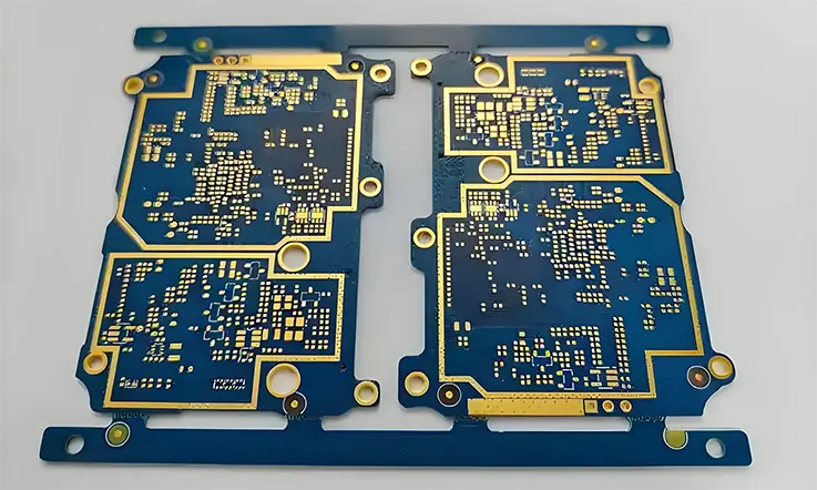
Designing a PCB stack-up with Rogers RO4450F involves careful attention to various aspects such as signal transmission, thermal management, and mechanical integrity. In high-demand applications like 5G communications, aerospace, and radar systems, selecting the right materials and arranging the layers properly ensures reliable performance in demanding environments.
The stack-up design process requires a focus on the interaction between materials, optimizing electrical performance while also addressing thermal dissipation and mechanical stresses. Rogers RO4450F is a core choice for high-frequency designs due to its stable dielectric constant and low loss, which helps maintain signal integrity in advanced technologies.
Multilayer PCB Stack-Up with Rogers RO4450F PCB & FR4
In a typical multilayer PCB stack-up, Rogers RO4450F is used for the high-frequency signal layers, while FR4 is chosen for the non-critical layers. This combination provides an efficient design that leverages the signal integrity benefits of RO4450F without significantly increasing costs.
The use of Rogers RO4450F for signal layers ensures that the signal attenuation and reflection losses are minimized, providing reliable signal transmission. On the other hand, FR4 is utilized in non-high-frequency layers, balancing material cost with performance demands.
Impedance Control & RF Signal Integrity in Rogers RO4450F PCB Stack-Ups
Managing impedance is a aspect of designing high-frequency PCBs, especially when using materials like Rogers RO4450F. Proper impedance control ensures that signals maintain their integrity without distortion or reflection.
Rogers RO4450F offers a stable dielectric constant, which helps maintain consistent impedance across the signal path. We can adjust design parameters, such as trace width, spacing, and layer thickness, to ensure the impedance is properly controlled, preventing signal degradation.
Example of Impedance Control:
●Material: Rogers RO4450F (Dk = 3.55)
●Trace Width: 6 mils (0.006 inches)
●Trace Spacing: 5 mils (0.005 inches)
●PCB Thickness: 62 mils (0.062 inches)
By adjusting these parameters, we can achieve the correct impedance, which ensures stable signal transmission and minimizes signal loss.
Hybrid Lamination Strategies – Combining Rogers RO4450F PCB with Other Materials
Using hybrid lamination strategies allows us to combine Rogers RO4450F with other materials such as PTFE or polyimide to meet specific application requirements. These materials can offer low loss or high thermal resistance, which can be essential in certain industries.
For instance, Rogers RO4450F is well-suited for signal layers requiring low loss, while other materials like FR4 may be used for non-critical layers, offering a cost-effective solution while maintaining high performance where needed.
Considerations for Hybrid Lamination:
●Thermal Conductivity: Combining Rogers RO4450F with PTFE can improve heat dissipation, which is useful in applications such as automotive radar.
●Mechanical Integrity: Rogers RO4450F is known for its high tensile strength, making it suitable for structural layers in high-performance designs.
●Cost-Effectiveness: Hybrid strategies allow us to balance premium materials with more economical options to reduce overall material costs.
By selecting the most appropriate materials for each layer, we can create cost-effective PCBs that meet the performance needs of demanding applications.
Thermal Management & Signal Integrity in Rogers RO4450F PCB Design
When designing high-frequency PCBs, maintaining stable performance under thermal and electrical stress is a major consideration. Rogers RO4450F PCB is often selected for its low dielectric loss and excellent thermal conductivity. Therefore, it suitable for 5G infrastructure, RF applications, and aerospace systems where signal precision and heat control are non-negotiable.
Poor thermal management can lead to signal degradation, impacting transmission accuracy and causing failures in RF circuits. Similarly, high-frequency applications demand materials with consistent dielectric properties to prevent unnecessary signal attenuation. The choice of Rogers RO4450F addresses these concerns, providing a balanced solution for engineers looking to optimize heat dissipation and signal transmission in a single platform.
Thermal Conductivity & Heat Dissipation in Rogers RO4450F PCB
Effective thermal conductivity is a must in high-power RF applications, where heat buildup can degrade component performance and shorten the lifespan of PCB assemblies. Rogers RO4450F offers a higher thermal conductivity than standard FR4, allowing for more efficient heat transfer across layers and through plated vias.
| Material | Thermal Conductivity (W/m·K) | Glass Transition Temp. (Tg, °C) | CTE (Z-axis, ppm/°C) |
| Rogers RO4450F | 0.6 | >280 | 32 |
| FR4 | 0.25 | 130-170 | 50-70 |
When designing with Rogers RO4450F, we can leverage copper planes, thermal vias, and heat sinks to further enhance thermal regulation. Proper layout planning ensures uniform heat distribution, preventing localized hotspots that could interfere with signal stability.
Additionally, the material’s coefficient of thermal expansion (CTE) is closely matched with copper, minimizing mechanical stress on plated through-holes (PTHs) and improving overall board reliability under temperature fluctuations.
Minimizing Dielectric Loss & Insertion Loss in Rogers RO4450F PCB
For microwave circuits and high-speed digital designs, excessive dielectric loss leads to weakened signal strength and reduced transmission efficiency. Rogers RO4450F is designed to tackle this issue by maintaining a low dissipation factor (Df), ensuring that high-frequency signals retain their integrity over longer distances.
| Material | Dielectric Constant (Dk, @10GHz) | Dissipation Factor (Df, @10GHz) | Insertion Loss (dB/inch @10GHz) |
| Rogers RO4450F | 3.5 | 0.004 | 0.35 |
| FR4 | 4.2-4.5 | 0.02-0.025 | 0.9-1.2 |
Insertion loss is another challenge in high-frequency circuits, where signal energy is gradually absorbed by the PCB material. RO4450F minimizes this effect by offering a low-loss tangent, reducing power loss and improving transmission clarity in applications like radar systems and satellite communications.
By optimizing trace geometry, selecting appropriate copper roughness, and ensuring a well-structured layer stack-up, our engineers can further reduce dielectric and insertion loss, enhancing overall circuit efficiency.
Plated Through-Hole (PTH) Reliability in High-Frequency Rogers RO4450F PCB
The durability of plated through-holes (PTHs) is a main factor in multilayer PCB designs, especially when exposed to frequent thermal cycling. Rogers RO4450F provides a mechanically stable foundation, reducing the risk of barrel cracking and ensuring strong electrical connections between layers.
| Material | CTE (Z-axis, ppm/°C) | PTH Reliability (Thermal Cycles to Failure @150°C) |
| Rogers RO4450F | 32 | >1,000 cycles |
| FR4 | 50-70 | <500 cycles |
Since high-frequency PCBs often require controlled impedance and multi-layer interconnects, maintaining PTH reliability is non-negotiable. The low CTE of RO4450F aligns well with copper plating, preventing stress-induced failures in high-temperature environments.
To further enhance mechanical strength, PCB manufacturers can implement via filling, resin reinforcement, and optimized copper plating thickness to extend the operational lifespan of RO4450F-based circuits.
How Rogers RO4450F PCB Enhances RF & Microwave Performance?
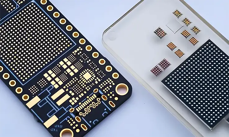
High-frequency applications require stable electrical performance and minimal signal distortion, particularly in RF and microwave circuits. As a result, professionals in industries focused on advanced communication systems often choose materials that offer precise impedance control, low signal loss, and reliable interconnect performance.
Rogers RO4450F PCB is designed to support these needs. Built with low-loss thermoset resin and ceramic reinforcement, it ensures low passive intermodulation (PIM), minimal crosstalk, and reliable function under demanding conditions. Let’s dive into the details of how Rogers RO4450F contributes to next-generation RF and microwave designs.
Low PIM (Passive Intermodulation) Design with Rogers RO4450F PCB
In wireless communication systems, PIM interference can disrupt signal clarity, leading to performance issues in cellular networks, satellite links, and high-power RF applications. Rogers RO4450F PCB is engineered to suppress PIM distortion, thanks to its low-loss material composition and stable dielectric properties.
Unlike traditional FR4-based RF circuits, which often introduce PIM due to material inconsistencies, Rogers RO4450F ensures a more uniform dielectric structure, reducing the chance of intermodulation distortion. Additionally, the compatibility of RO4450F with low-profile copper foils further minimizes PIM generation, making it a strong choice for base stations and antenna applications.
For those refining circuit designs, careful attention to trace layout, via positioning, and connector selection can help minimize unwanted intermodulation effects, leading to cleaner signal transmission.
Minimizing Signal Loss & Crosstalk in Rogers RO4450F PCB-Based Circuits
When dealing with high-frequency transmission, signal loss and crosstalk can disrupt RF and microwave performance. Rogers RO4450F PCB addresses these concerns by offering:
●Low dielectric loss (Df) – Reducing energy dissipation along the signal path.
●Stable dielectric constant (Dk) – Keeping impedance predictable across various frequencies.
●Enhanced copper adhesion – Ensuring smooth surface roughness, which lowers conductor loss.
Crosstalk is another issue in dense circuit layouts, where signals on adjacent traces interfere with each other. RO4450F’s low-loss dielectric helps control this issue by maintaining consistent electrical properties, allowing for better isolation between traces.
To further reduce crosstalk, designers can:
●Maintain proper spacing between RF transmission lines.
●Use grounded coplanar waveguides (GCPW) or stripline configurations.
●Optimize layer stack-up to provide better shielding against unwanted coupling.
Achieving Stable Performance in Extreme Environments with Rogers RO4450F PCB
RF and microwave applications often operate in harsh conditions, including high-altitude aerospace systems, outdoor 5G base stations, and military-grade radar units. Materials used in these settings must handle temperature shifts, humidity exposure, and mechanical stress without altering electrical performance.
Rogers RO4450F PCB is well-suited for these environments due to its:
●Low coefficient of thermal expansion (CTE) – Matching copper’s expansion rate to reduce mechanical stress.
●High glass transition temperature (Tg) – Preventing warpage and maintaining dimensional accuracy.
●Moisture resistance – Guarding against performance degradation in humid conditions.
Comparing Rogers RO4450F PCB with Other Rogers PCB Laminates, ISOLA, Teflon, Taconic, and RT/duroid®
When choosing high-frequency PCB substrates, it’s essential to consider factors like electrical performance, manufacturing compatibility, and long-term stability. Rogers RO4450F PCB is often used in advanced communication technologies, defense electronics, and precision measurement systems. However, alternative materials such as Isola, Teflon, Taconic, and RT/duroid® can also serve similar functions, depending on the specific requirements of each application.
This section compares Rogers RO4450F PCB against these materials in terms of signal integrity, thermal stability, and manufacturing feasibility.
Rogers RO4450F PCB vs. Isola – Performance Differences That Matter
Isola produces high-speed digital and RF PCB materials, including laminates like IS620 and Astra MT77, which are often used in microwave and millimeter-wave applications. How does Rogers RO4450F PCB compare?
| Attribute | Rogers RO4450F | Isola IS620 / Astra MT77 |
| Dielectric Loss (Df) | 0.004 (at 10 GHz) | 0.0017(at 10 GHz) |
| Thermal Expansion (CTE) | 17 ppm/°C | 12 ppm/°C |
| Copper-Clad Lamination | Standard, compatible with FR4 | May require additional treatments |
| Temperature Resistance | 280°C Tg | 270°C Tg |
| Fabrication Process | Standard PCB processes | Requires specialized steps |
●Signal Integrity – Isola IS620 / Astra MT77 exhibits lower dielectric loss (Df) than Isola materials, making it a better option for long-distance, high-frequency signal transmission.
●Thermal Expansion Compatibility –Isola IS620 / Astra MT77 has a lower CTE, reducing stress between plated through-holes (PTH) and copper layers in multilayer designs, which minimizes failures due to thermal cycling.
●Manufacturing Simplicity – RO4450F PCB is compatible with standard PCB fabrication processes, whereas some Isola materials may require additional steps, increasing production costs and lead times.
For projects involving antenna arrays, phased array radar, or millimeter-wave front-end modules, Isola IS620 / Astra MT77 offers better signal retention across a wide frequency range.
Rogers RO4450F PCB vs. Teflon and Taconic – Which One Works for Your RF PCB?
Teflon-based materials, such as those from Taconic, are often used in ultra-low-loss applications. However, these materials come with challenges that Rogers RO4450F PCB addresses effectively.
| Attribute | Rogers RO4450F | Teflon (Taconic) |
| Dielectric Loss (Df) | 0.004(at 10 GHz) | 0.0023 (at 10 GHz) |
| Thermal Expansion (CTE) | 17ppm/°C | 17-18 ppm/°C |
| Mechanical Durability | Ceramic-filled, more rigid | Prone to warping and cracking |
| Fabrication Process | Standard, compatible with FR4 | Requires plasma treatments |
| Cost | More affordable | Higher processing costs |
●Fabrication Challenges – Teflon substrates are prone to warping during processing, often requiring plasma treatments to ensure proper hole-wall adhesion, while RO4450F PCB supports standard processing techniques.
●Mechanical Durability – RO4450F PCB utilizes a ceramic-filled structure, which enhances structural strength and thermal stability compared to pure Teflon-based materials.
●Cost Considerations – Teflon materials generally have higher processing costs, making RO4450F PCB a more cost-effective alternative.
For applications that demand low loss while maintaining manufacturing feasibility, RO4450F PCB strikes a practical balance.
RT/duroid® vs. Rogers RO4450F PCB – Best Options for High-Reliability PCBs
RT/duroid® laminates (e.g., RT/duroid® 5880 and 6002) are often used for applications where low loss and high thermal stability are required. However, there are notable differences when compared to RO4450F PCB:
| Attribute | Rogers RO4450F | RT/duroid® 5880 / 6002 |
| Dielectric Loss (Df) | 0.004 (at 10 GHz) | 0.004 (at 10 GHz) |
| Thermal Expansion (CTE) | 17 ppm/°C | 15 ppm/°C |
| Mechanical Durability | High rigidity, reduces flexing | Moderate rigidity, more flexing |
| Multilayer Compatibility | Easy integration with FR4 | Requires specialized lamination |
| Cost | Cost-effective | Expensive |
●Dielectric Performance – RT/duroid® materials are designed to perform well at very high frequencies, excelling in applications where minimizing signal loss is necessary. These materials offer low attenuation and high thermal stability in demanding environments.
●Structural Strength – RO4450F PCB offers greater rigidity, reducing board flexing and improving overall durability.
●Multilayer Compatibility – RO4450F PCB integrates more easily with FR4 and other hybrid stack-ups, whereas some RT/duroid® materials require specialized lamination techniques.
For LEO satellites and aerospace systems, RO4450F PCB provides a balanced option when considering cost, mechanical strength, and manufacturing practicality.
Key Applications of Rogers RO4450F PCB in 5G, Aerospace & RF Circuits
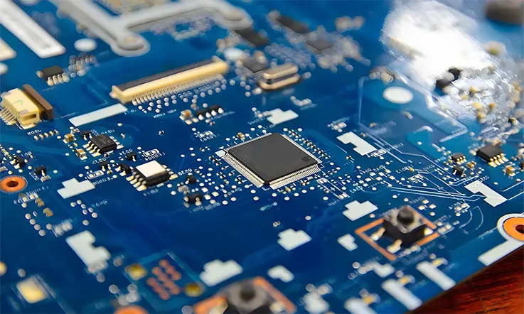
The demand for high-frequency PCB materials has never been higher. With 5G networks scaling up, aerospace electronics pushing boundaries, and RF systems requiring precision, selecting the right laminate is not just about performance—it’s about ensuring smooth operation across a wide range of conditions.
Rogers RO4450F PCB is widely used in wireless infrastructure, radar, and microwave communication systems, making it a reliable choice in industries where low loss, temperature stability, and manufacturing efficiency define success. Let’s explore where this material fits best and why.
How Rogers RO4450F PCB Supports 5G Base Stations & IoT Networks?
5G isn’t just about speed—it’s about efficient signal transmission across millimeter-wave bands, network densification, and ultra-low latency communication. The hardware behind 5G must be able to:
●Maintain low signal loss across high-frequency bands like 28 GHz and 39 GHz.
●Ensure impedance stability in complex multilayer designs.
●Withstand temperature shifts and power variations in outdoor environments.
RO4450F PCB meets these requirements with a low dissipation factor (Df) and well-controlled dielectric constant (Dk), making it a strong option for 5G antennas, RF front-end modules, and power amplifiers.
For IoT applications, where compact, multi-layered circuits power smart grids, connected vehicles, and industrial automation, RO4450F PCB delivers stable performance while keeping manufacturing straightforward.
Why Rogers RO4450F PCB is Used in Aerospace & Military Systems?
Electronics in aerospace and defense don’t just need to work—they need to last. Whether it’s satellite communications, radar tracking, or avionics, PCB materials must offer:
●Reliable electrical performance across a wide temperature range.
●Low passive intermodulation (PIM) to minimize interference in sensitive RF systems.
●High mechanical strength to endure shock, vibration, and rapid altitude shifts.
RO4450F PCB is often selected over PTFE-based laminates for military radar, electronic warfare systems, and satellite uplink modules. Its ceramic-filled composition provides added stability, making it a dependable choice for extreme environments.
RF & Microwave Circuitry – Maintaining Signal Integrity with Rogers RO4450F PCB
Managing signal attenuation, impedance mismatches, and crosstalk is a constant challenge in RF applications. . High-frequency circuits—such as those used in microwave radios, automotive radar, and GPS systems—rely on PCB materials that:
●Keep insertion loss minimal for consistent signal strength.
●Support plated through-hole (PTH) durability in high-layer count PCBs.
●Prevent distortion in high-power RF transmissions.
Rogers RO4450F PCB is frequently chosen for low-noise amplifiers, RF filters, and power dividers due to its low Df and predictable dielectric properties. It allows RF signals to travel efficiently, reducing the need for excessive gain adjustments.
How to Choose the Right Manufacturer & Supplier for Rogers RO4450F PCB?
Choosing the right PCB supplier goes beyond just looking at costs. When dealing with high-frequency laminates like Rogers RO4450F PCB, precision in manufacturing determines whether a design succeeds or fails. A skilled supplier guarantees stable impedance, reliable electrical performance, and durability over time, making sure your circuits perform as expected in real-world conditions.
For industries like 5G, aerospace, and RF engineering, it’s not enough for a manufacturer to just “build a PCB.” They need the right equipment, materials, and expertise to handle ceramic-filled hydrocarbon laminates properly. Here’s what to consider when selecting a trusted Rogers RO4450F PCB manufacturer.
What to Look for in a Rogers RO4450F PCB Manufacturer?
Unlike conventional FR4, Rogers RO4450F PCB requires tighter process controls and specialized fabrication techniques. The material has low dielectric loss, stable performance across frequencies, and precise impedance characteristics, but only if processed correctly.
When evaluating manufacturers, consider:
●Experience with high-frequency PCBs – Ask for documented projects involving 5G antennas, radar systems, or microwave circuits.
●Advanced processing capabilities – Does the facility support laser direct imaging (LDI) for fine-line etching? Can they handle hybrid stack-ups with PTFE and FR4?
●Material sourcing – Are they using genuine Rogers RO4450F laminates from approved distributors?
●Quality control & testing – Do they perform PIM analysis, impedance testing, and thermal cycling validation?
The right manufacturer will have a structured workflow to fabricate high-frequency PCBs while maintaining consistent quality standards.
Supply Chain Challenges & How to Avoid Fake Rogers RO4450F PCB Materials
Not all materials labeled as “Rogers” are what they claim to be. Counterfeit laminates circulate in the supply chain, leading to unexpected signal loss, poor thermal performance, and failure in real-world applications.
To avoid these risks:
●Verify supplier credentials – Work with Rogers-authorized distributors to ensure material authenticity.
●Request certification – Every batch should come with a Certificate of Compliance (CoC) and dielectric property validation.
●Check fabrication reports – Ensure the Dk, Df, and copper adhesion strength match Rogers’ official specifications.
A trusted PCB supplier will have direct partnerships with recognized material providers, eliminating any chance of substitution.
Why China Has Become a Preferred Source for High-End Rogers RO4450F PCB?
China is now a global leader in high-frequency PCB manufacturing due to its advanced facilities, scalable production capacity, and strong material sourcing networks.
| Manufacturing Advantage | How It Benefits Rogers RO4450F PCB Production? |
| State-of-the-Art Fabrication | Facilities optimized for microwave, radar, and 5G RF circuit boards. |
| Scalability | Supports small-batch prototypes to large-volume orders. |
| Material Availability | Faster access to authentic Rogers laminates from certified suppliers. |
| Cost & Lead Time Optimization | Lower production costs and shorter turnaround times. |
●Advanced fabrication facilities optimized for Rogers RO4450F, Teflon-based laminates, and hybrid constructions.
●Scalable production supporting both small-batch prototyping and high-volume manufacturing.
●Strong material sourcing networks that ensure fast access to authentic Rogers laminates.
With a growing demand for high-performance RF circuits, many manufacturers in China now specialize in microwave PCBs, phased array radar boards, and 5G hardware. This makes it easier to balance cost, turnaround time, and fabrication precision.
Why Choose Us as Your RO4450F PCB Supplier?
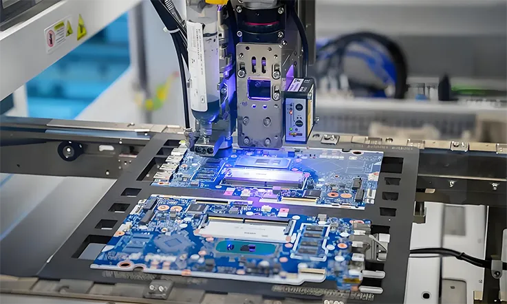
As a leading PCB manufacturer, we take pride in offering high-performance RO4450F PCB manufacturing, designed to meet the demanding needs of complex applications. Our expertise in Rogers PCB fabrication ensures that we deliver high-quality, defect-free multilayer boards with precise control over performance.
We manufacturing RO4450F PCBs are RoHS-compliant, making them environmentally friendly and well-suited for applications ranging from digital circuits to backhaul radio systems. Rigorous testing, including E-testing and AOI inspections, guarantees that each board meets our high standards, ensuring error-free delivery.
We know that getting good value without compromising on quality matters, which is why we provide competitive pricing while ensuring durability and performance. Our team is always ready to assist with PCB design, layout support, and technical guidance, available 24/7. With many of our professionals having over ten years of experience, you can trust that you’re working with experts who are fully dedicated to your needs.
Rogers RO4450F PCB & FAQ
1.Can Rogers RO4450F be used for flexible PCBs?
No, Rogers RO4450F is a rigid material and is typically used in rigid PCB designs rather than flexible ones.
2.What are the typical thicknesses of Rogers RO4450F available in the market?
Rogers RO4450F is available in various thicknesses, commonly ranging from 0.008″ to 0.062″ (0.2 mm to 1.6 mm).
3.Is Rogers RO4450F PCB suitable for high-voltage applications?
It is not specifically designed for high-voltage applications, but it can handle moderate voltage levels typically seen in RF and microwave circuits.
4.What is the maximum frequency Rogers RO4450F can operate at without performance degradation?
Rogers RO4450F can efficiently operate at frequencies up to 40 GHz, with minimal signal degradation, making it suitable for high-frequency applications like RF and microwave.
Our services
Rogers PCB Laminates & Series

