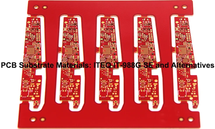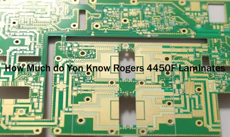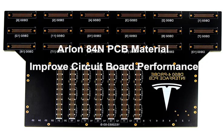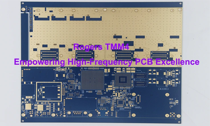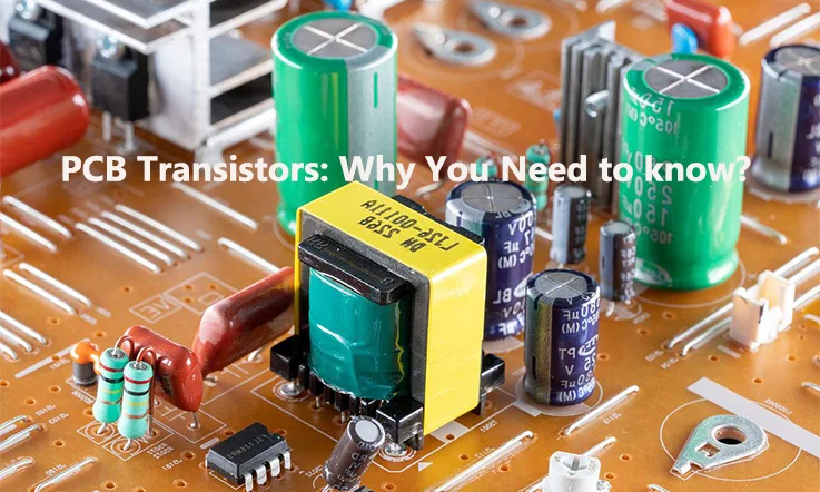
Printed circuit boards (PCBs) are an integral part of modern electronic devices. Contained within these boards are an array of components that come together to power today’s technology. Chief among these components are transistors, the fundamental building blocks that enable the flow of electrical signals. Transistors deposited and connected directly onto PCB surfaces play a crucial role in device functionality.
Introduction of PCB Transistor
The transistor is one of the most fundamental and ubiquitous electronic components used in circuit design. Since their inception in the mid-20th century, transistors have formed the building blocks of modern electronics.
Printed circuit boards provide a means to construct complete electronic systems by allowing for the dense packaging and interconnection of both passive and active components. Surface mounting transistors directly onto PCBs has become common practice, enabling the placement of transistors in close proximity to other devices for optimized circuit performance.
There are a variety of transistor types suitable for implementation within PCB circuitry. Bipolar junction transistors (BJTs) and field effect transistors (FETs) cover the majority of applications, with MOSFETs proving particularly popular. Key factors such as operating voltage, current handling capabilities, packaging, and switching speed help engineers select the right transistor for a given design role.
Once laid out on the PCB, transistors undergo reflow soldering during the assembly process to permanently bond their leads. This precision mounting enables an electrical interface between transistor terminals and copper circuit traces. Discrete PCB transistors then operate as building blocks within circuit functions like amplification, buffering, switching and logic operations.
How Many Types PCB Transistor
This section provides an overview of the two main transistor configurations used in printed circuit board designs: NPN and PNP. Understanding the fundamental differences between these types is essential for circuit design and transistor selection.
NPN transistors have a collector, base, and emitter terminal arrangement of negative-positive-negative polarity respectively. Conversely, PNP transistors feature a positive-negative-positive terminal configuration.
These two types can further be categorized into bipolar junction transistors (BJTs) and field-effect transistors (FETs). BJTs rely on the injection of both majority and minority carriers for operation, with current flow controlled by a small base current. FETs conduct current via an electric field; minority carriers are typically not involved.
BJTs include bipolar NPN and PNP types suited for general purpose amplification and switching applications. FET configurations consist of N-channel and P-channel MOSFETs favored for high input impedance and voltage control. Gallium Arsenide FETs provide very high operating frequencies.
It is critical to understand the similarities and differences between these transistor classes and polarities when designing circuits. Selecting the proper configuration ensures a device can fulfill its intended functional role within a PCB system.
What is SMD Transistor?
In the context of mounting transistors on a circuit board, a commonly used method is Surface Mount Device (SMD) Transistors. This approach offers cost advantages compared to other methods of transistor attachment. However, it is important to note that SMD transistors can be susceptible to environmental strains and vibrations, which can make them more fragile.
Alternatively, the Through-Hole approach provides an alternative method for incorporating transistors, where metal prongs are inserted into perforations on the board. Although this method can be more expensive and time-consuming to manufacture, it offers increased reliability and durability.
When deciding on the appropriate approach, it is advisable to consider factors such as the intended purpose of the device, budget constraints, and specific application requirements. By carefully evaluating these aspects, both the manufacturer and the client can save valuable time and ensure a successful outcome.
How to Read PCB Transistors?
To read PCB transistors, you can follow these steps:
1. Identify the transistor package: Transistors can come in various packages, such as TO-92, SOT-23, SOT-89, etc. Identify the package type of the transistor you want to read.
2. Locate the transistor on the PCB: Look for the transistor on the printed circuit board (PCB). It will typically have three terminals, labeled as the collector (C), base (B), and emitter (E).
3. Determine the transistor type: Transistors can be either bipolar junction transistors (BJT) or field-effect transistors (FET). BJTs have two types: NPN and PNP, while FETs have two types: N-channel and P-channel. Determine the type of transistor you are dealing with.
4. Identify the pinout: The pinout refers to the arrangement of the terminals on the transistor. Each transistor type and package has a specific pinout. Consult the datasheet or a transistor identification guide to determine the pinout for your specific transistor.
5. Read the markings: Transistors often have markings on their packages to indicate their specifications. Look for alphanumeric codes, symbols, or color codes on the transistor. These markings can provide information about the transistor’s type, voltage ratings, current ratings, and other characteristics.
6. Refer to the datasheet: If you have access to the datasheet for the transistor, it will provide detailed information about its electrical characteristics, pinout, and usage. The datasheet is the most reliable source of information for a specific transistor.
By following these steps and using reference materials like datasheets and transistor identification guides, you can read and understand the specifications of PCB transistors.
How Do you Test PCB Transistors?
Testing PCB transistors is a crucial step to ensure their proper functionality within circuits. Failure of a transistor can lead to circuit malfunctions, highlighting the importance of thorough testing. To assist you in this process, here is a step-by-step tutorial for testing a PCB transistor:
Step 1:
Prior to testing the transistor, ensure that the circuit is switched off and there is no electrical current flowing through it. Disconnect the battery and unplug the AVC power connection. To discharge any stored power, safely touch the two terminals of a capacitor with a metal object, such as a screwdriver with insulated handle.
Step 2:
Identify the collector, base, and emitter leads of the transistor you intend to test. Some transistors have labeled leads for easy identification, often marked as C, B, and E. As lead placements may vary, it is advisable to consult a catalog from your electronics supplier to confirm the correct orientation.
Step 3:
If your digital multimeter has a diode setting, use it for this step. Otherwise, set the meter to the ohms setting. In the case of an analog environment, set the meter to a low ohm scale.
Step 4:
Place one lead of the meter on the base lead and the other lead on the collector lead. Check the meter reading for the collector in both base-collector directions. Analyze the reading and provide appropriate advice. A properly functioning transistor will display a reading in one direction and infinity (∞) in the other.
Step 5:
Next, touch one lead of the meter to the base and connect the other lead to the emitter. Check the meter reading for the emitter on the base in both directions. Reverse the leads to read the meter in the opposite direction. Similar to step four, expect one reading to display around 600 and the other to show an infinite value (∞).
Step 6:
If the reading is significantly different from 600, it indicates that other components might be affecting the reading. In such cases, remove the base lead from the PCB by melting the solder that attaches it. Use the meter to check both routes from the base to the collector and from the base to the emitter. Once the readings are obtained, melt the solder, insert the lead into the board’s hole, and reattach it securely.
Step 7:
In the final step, based on the test results, you can determine if the collector or base-emitter readings indicate zero (0) in both directions or if they show infinity (∞) in both directions. Zero readings indicate a short circuit, while infinity readings suggest an open transistor diode.
For a more comprehensive understanding of inspecting a circuit board, you may refer to additional resources available.
Importance of Transistors in Circuit Boards
The transistor has come a long way since its origins in the early computer industry. Initially utilized as key components in some of the first digital computers, transistors demonstrated their ability to be clustered together to form functional microprocessors capable of executing programmed instructions on a single integrated circuit (IC).
Transistors now pervade modern electronic devices powering entertainment systems such as game consoles and MP3 players as well as smartphones, cameras, and computer hard disks. They are virtually ubiquitous, embedded in nearly every IC that underpins digital systems and technologies. Frequently implemented directly into circuit board designs, transistors efficiently manage signal flow into and out of devices while maintaining compact footprints suited for integration into many system architectures.
Presently, transistors remain integral to electronics, seamlessly interfaced into circuitry at both the system and component level. Their prevalence stems from the versatility provided by configurations like integrated circuits (ICs), which consolidate numerous densely packaged transistors linked by internal wiring on a single silicon chip.
Applications have also broadened to encompass diverse functions. Transistors excel in both low-frequency, high-power applications requiring efficient AC-DC conversion as well as high-frequency use cases that generate radio frequencies from oscillator circuitry. Their broad applicability across operating regimes has been instrumental to advancing technologies spanning communications, computing, and beyond. Continued transistor innovation remains crucial to developing next-generation solutions empowering individuals and industries alike in the digital era.
The Source of Reliable PCB Transistors: JarnisTech
We understand that ensuring product quality is paramount when making critical business decisions. To achieve this, well-functioning PCB transistors integrated into printed circuit boards are essential.
Equally important is evaluating a manufacturer’s proven ability to deliver against committed timelines. Maintaining schedule adherence is crucial, especially for mission-critical projects.
As an experienced PCB fabrication partner, JarnisTech is well-positioned to meet both of these core requirements. With extensive expertise in transistor-based circuit design and production, we can develop solutions that precisely meet your PCB transistor specifications.
Our lean manufacturing infrastructure and processes also facilitate reliable on-time completion of even complex, high-mix PCB orders. Customer focus and responsiveness are central to our operations.
We invite you to discuss your specific PCB requirements with one of our representatives. JarnisTech aims to deliver an attentive, solutions-oriented experience for all engagement throughout the development and production lifecycle. Please contact us to learn how we can help advance your product and business objectives.
Conclusion
It is crucial to determine the specific purpose of a PCB transistor before procuring one, considering its diverse responsibilities within a device. Additionally, it is important to carefully consider the transistor’s classification to ensure it aligns with the intended application before making a purchase.
Throughout this article, we have demonstrated that although PCB transistors may appear simple at first glance, understanding their functionality requires a comprehensive approach. At JarnisTech, we sincerely hope that this article has provided valuable insights into the detailed understanding of PCB transistors.
If you are still searching for a reliable manufacturer to design and assemble your circuit boards, look no further than JarnisTech. With our extensive industry experience, we guarantee professional and meticulous handling of your orders.
Please feel free to send us an inquiry or request a quote today, and we will promptly address any questions or concerns you may have.

