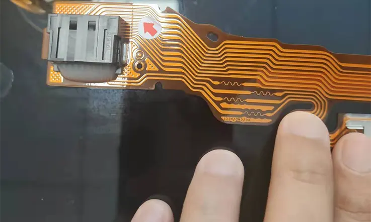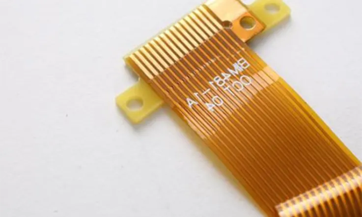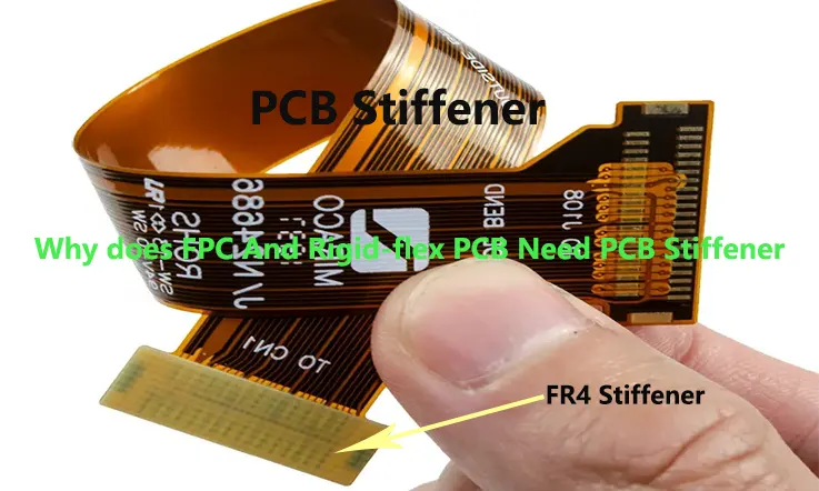
Flexible Printed Circuit Boards (FPCs) are a type of circuit board that utilizes polyimide as the substrate. FPCs are highly dependable and offer good flexibility. They are also characterized by their thinness, suppleness, lightness, and adaptability.
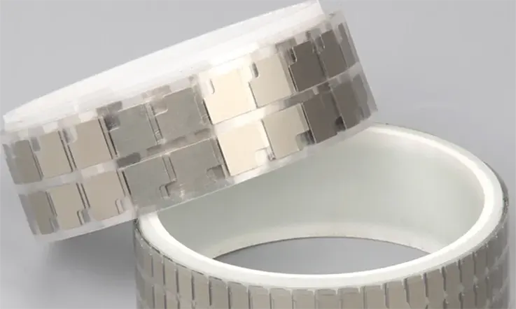
At times, in order to reduce flexibility and provide adequate support for the components during assembly, certain areas of the flex PCBs need to be intensified. This is accomplished through the use of a stiffener, which is a hard material applied to the intensified area. Stiffeners play a crucial role in maintaining board stability during subsequent soldering processes and overall assembly.
Aside from component support, stiffeners are also employed for heat dissipation. Certain stiffeners with specialized designs can also serve as assembly aids. As the most common method for strengthening FPCs, the addition of stiffeners is a crucial element in ensuring reliable and robust flexible printed circuit boards.
What Is a Stiffener in Flex PCB ?
PCB stiffeners play the critical role of providing mechanical support during the assembly of the PCB, although they are not an electrical component of the board. They offer extra machinery to lend the circuit board the required mechanical rigidity.
In the majority of cases, stiffeners are applied to the same side of the flex PCB. However, in certain instances, the stiffeners need to be pressed onto both sides, leading to multiple lamination cycles that increase costs and lead time. In addition, stiffeners need to be accurately and completely stated in the Gerber file set. Also, stiffeners on the top and bottom layers must be placed in separate mechanical layers.
While flexible PCBs provide numerous advantages, they have certain limitations, one of which is excessive flexibility where rigidity is needed. To resolve this problem, PCB professionals have developed stiffeners to provide the necessary mechanical support. Human expertise plays a crucial role in the development of these stiffeners, ensuring they perform effectively in various circumstances.
Stiffener Materials
Stiffeners used in the manufacturing of flexible printed circuit boards (PCBs) are typically constructed of materials like Polyimide, FR-4, Aluminum, and Stainless Steel. Proper selection of the stiffener material is crucial because different types of stiffeners offer varying benefits in specific applications.
The choice of stiffener material will depend on several factors, including the particular manufacturing requirements and the end-use of the flex PCB. The use of inappropriate stiffener materials may lead to defects or limitations in the overall functionality of the circuit board. Therefore, it is critical to evaluate and identify the ideal stiffener material for a specific application during the PCB design and manufacturing process.
FR-4 Stiffeners
FR-4 stiffeners play a vital role in providing mechanical support for flex design regions where connectors and/or components are joined, preventing the flex circuit from bending near these junctions. Without FR-4 stiffeners, the circuit board’s bending could cause broken or compromised solder junctions.
To avoid hole misalignment during manual bonding, the stiffener holes (access holes) must be enlarged by 0.15 mm on each side when the dimensions and location of the flex circuit and FR4 stiffener match. For the FR-4 stiffener bonding process, drilling, registration, and pre-tack of prepreg or adhesive are mandatory.
Careful execution of each step in the FR-4 stiffener bonding process is crucial, requiring precise attention to detail. Not only will this prevent hole misalignment, but it will also help deliver durable and reliable PCBs.
Polyimide Stiffeners
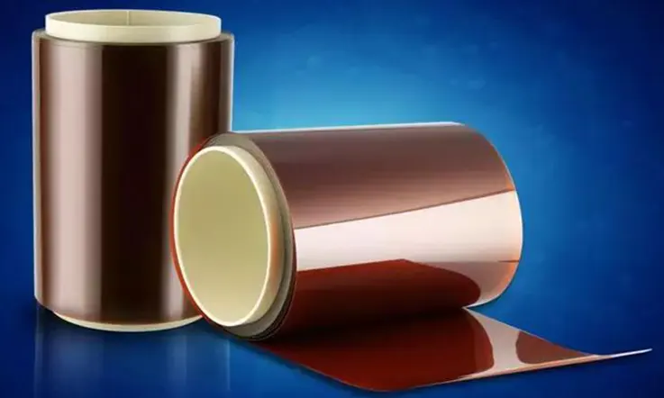
Polyimide (PI) stiffeners are a widely used type of stiffener for supporting FPC gold fingers that will be inserted into ZIF connectors. To ensure a reliable connection, the connector specifications require that the exposed ZIF contact fingers on the flexible circuit have a specific thickness. Typically, the two most common ZIF finger thicknesses are 0.3mm and 0.2mm, with each thickness having a defined tolerance ranging from 0.03 mm to 0.05 mm.
Proper selection of stiffener material and dimensions is critical in the FPC manufacturing process, especially when accommodating ZIF connector requirements. Using PI stiffeners can provide excellent mechanical support and increase the durability of the circuit board while helping to meet the specific thickness tolerances required by the connector. Careful attention to these specifications during circuit design and manufacturing can help to ensure dependable and high-quality flex circuits.
Aluminum and Stainless Steel Stiffeners
Metal stiffeners, such as aluminum and stainless steel, are commonly used but require customization, resulting in higher costs and longer turnaround times compared to polyimide and FR-4 stiffeners.
Aluminum is an ideal choice for heat dissipation, while stainless steel is preferred in situations where there is limited space for stiffeners but more support is required for the components than what an equivalent thickness FR-4 stiffener can provide.
The bonding process for aluminum stiffeners involves drilling, milling, registration, and prepreg pre-stacking. For stainless steel stiffeners, the bonding process includes drilling, laser cutting, registration, and prepreg pre-stacking.
While metal stiffeners offer significant benefits, they require additional customization and careful selection to support the specific application. By adhering to proper design and manufacturing procedures, including the appropriate choice and use of stiffener materials, manufacturers can ensure that they deliver reliable and high-quality flex circuits that meet specific performance requirements.
Flexible PCB Stiffener Requirements
Compliance with PCB manufacturing design guidelines is crucial when selecting a stiffener for a flex PCB. Customized flex PCB stiffeners may not be available from all PCB manufacturers; therefore, consultation with the manufacturer is recommended when specific layout or design requirements are necessary. This ensures that a customized stiffener is delivered when required, and ensures compliance with the manufacturer’s standards and regulations such as those set by OSHA and UL.
The criteria for a proper stiffener are as follows:
● The stiffener should not have sharp edges.
● Stiffness should be between 0.25-0.75 MPa (15-40 psi).
● The stiffener must be made using non-conductive materials such as PTFE, PET, and sheet metal.
● Applying a specified load with flex circuits on only one side should not result in permanent deformation of the rigid PCB.
● The stiffener should not cause a failure of the rigid PCB when a specified load is applied with flex circuits on only one side.
● The stiffener must be compatible with other layers, printed circuit boards, and components used in rigid-flex circuits and rigid PCBs.
● The stiffener should have a smooth surface finish to reduce the damage to flexible circuit board fabrication processes during manufacturing.
By carefully selecting and adhering to the above criteria, manufacturers can ensure that stiffeners are chosen appropriately, and resulting flex circuits and rigid PCBs are robust, durable, and meet all performance and regulatory requirements.
FPC Stiffener Thicknesses
Given the thinness of the flexible circuit board, PCB designers must carefully consider the thickness of the PCB stiffener during the design process. Neglecting this factor can impact on the performance and reliability of the flexible PCB, especially in demanding applications such as military and aerospace.
At our flex circuit fabrication facilities, we offer a variety of PCB stiffener materials, including Polyimide (PI), FR4, Stainless Steel, and Aluminum. Each type of FPC stiffener is available in a range of thicknesses to accommodate different design requirements.
By providing a range of stiffener materials and thicknesses, we give our clients the flexibility to select the most appropriate options to suit their particular application needs. Through careful consideration of these specifications, our clients can ensure optimal performance, durability, and high quality for their flexible circuits.
| Stiffener Material | Usual Thickness | Unusual Thickness |
| Polyimide (PI) | 0.05mm (2mil) 0.075mm (3mil) 0.1mm (4mil) 0.125mm (5mil) 0.15mm (6mil) | 0.175mm (7mil) 0.2mm (8mil) 0.25mm (10mil) 0.225mm (9mil) 0.25mm (10mil) 0.275mm (11mil) |
| FR-4 | 0.2mm (8mil) 0.3mm (12mil) 0.4mm (16mil) 0.5mm (20mil) 0.6mm (24mil) 0.7mm (28mil) 0.8mm (32mil) 1.0mm (39mil) 1.2mm (47mil) 1.5mm (59mil) | 0.9mm (35mil) 1.1mm (43mil) 1.3mm (51mil) 1.4mm (55mil) 1.6mm (63mil) |
| Aluminum | 0.2mm (8mil) 0.25mm (10mil) 0.3mm (12mil) 0.35mm (14mil) 0.4mm (16mil) 0.5mm (20mil) 1.5mm (59mil) | 0.15mm (6mil) 0.45mm (18mil) |
| Stainless Steel | 0.15mm (6mil) 0.2mm (8mil) | / |
In choosing the thickness for the PCB stiffener, we offer a variety of widely available thickness measurements. Alternatively, we can provide bespoke measurements to meet specific design requirements. Whatever the choice of thickness, it is essential to ensure consistency across the entire circuit. Uniformity in the circuit’s thickness is vital to ensure the proper functioning of the flexible PCB and to achieve optimal performance and reliability. At our flex circuit fabrication facilities, we provide precision engineering and quality control that adhere to stringent standards for uniformity across the entire circuit. Our expertise and attention to detail ensure that we deliver reliable, high-quality flex circuits that meet the unique needs of our customers.
Design Considerations for FPC and Rigid-flex Stiffener
Some essential design considerations for FPC and rigid-flex stiffener include:
● Material Selection: Careful consideration of materials used is required due to the flexibility and multi-layered nature of the designs. The selection of materials can have a significant impact on the overall performance, cost, and durability of the design.
● Thickness and Height Considerations: Both the thickness and height of the flexible and rigid portions of the design must be carefully considered to ensure proper assembly, performance, and reliability. Factors like the number of layers, component density, and required trace width must be taken into account for accurate thickness determination.
● Placement and Orientation of Components: Component placement and orientation are essential to ensure proper function and reliability of the design. The designer must consider factors like the flexibility of the materials, the location of stress points, and the effects of thermal expansion and contraction.
● Manufacturing Processes: FPC and rigid-flex stiffener designs require specialized manufacturing processes that must be considered during the design phase. The designer must consider factors like adhesive bonding, lamination, and drilling.
● Environmental Considerations: FPC and rigid-flex PCB stiffener designs must also be designed to withstand various environmental conditions like temperature extremes, moisture, and chemical exposure. Factors like material selection and conformal coating can aid in ensuring reliability in such harsh environments.
Why Do You Need Stiffener for Your Flexible and Rigid-flex PCB ?
● Flexible printed circuit boards (PCBs) are designed to bend easily due to the use of flexible materials like Polyimide. However, excessive bending can damage both the board and the circuit. To overcome this issue, flex PCB stiffeners are used to provide rigidity at specific spots on the board. This prevents areas from bending excessively, thereby ensuring that the board lasts longer.
● High component density on a flexible PCB requires the use of either a rigid material for that section, making the board rigid-flex, or stiffeners to support the weight of the components and ensure the board’s longevity. Stiffeners play a significant role in enhancing the durability of flexible circuits, allowing for greater component density.
● For surface-mount devices and through-hole components, a strong and reinforced board is necessary to prevent failure. Stiffeners provide reinforcement to such components, ensuring that they retain their position without damage.
● Connectors on flexible boards need an additional layer of support to prevent them from detaching or failing. Stiffeners are used to support these connectors by providing additional rigidity beneath them.
● Importantly, stiffeners can be added after the fabrication of the PCB and can boost the thickness of the circuit in targeted regions, without adding complexity or difficulty in the process. In summary, a flex PCB stiffener offers a powerful solution for achieving physical reinforcement in flexible PCB designs and maintaining a high level of functionality and durability across specific areas of the PCB.
Advantages of Using FPC and Rigid-flex Stiffener
Some advantages of using FPC and rigid-flex stiffener include:
● Decreased Board Space: FPC and rigid-flex designs take up less space than traditional PCBs, providing a compact solution for electronic devices with space constraints.
● Improved Reliability: Compared to traditional PCBs, FPC and rigid-flex designs have higher reliability since they are less prone to damage from vibration, shock and temperature changes. The flexible components of FPC designs allow them to bend and flex without breaking, making them more durable.
● Increased Durability: FPC and rigid-flex designs can resist environmental stress caused by humidity, temperature changes and other harsh conditions, making them more durable than traditional PCBs.
● Greater Design Flexibility: The flexibility of FPC and rigid-flex designs enables designers to build compact and flexible circuits with varying shapes and sizes, suitable for unusual form factors or demanding, space-constrained applications.
As a result, FPC and rigid-flex designs provide a flexible and durable solution for applications where reliability and compact footprint are essential.
When Do FPC and Rigid-flex PCBs Need Stiffeners ?
● The use of PCB stiffeners is a necessary technique for enhancing the reliability and durability of flexible and rigid-flexible printed circuit boards (PCBs) in various designs and applications. Specifically, FR-4 PCB stiffeners are often utilized when faced with certain conditions, including localized bend constraints, components placed in a flex zone, ZIF (Zero Insertion Force) thickness requirements, and the need to manage heat dissipation using aluminum and stainless-steel stiffeners.
● Additionally, the installation of heavy components in a flex zone can cause stress on the flex material, necessitating the use of PCB stiffeners. Moreover, creating a flat and stiff surface on the flex for the installation of SMT pads components is achievable with the use of stiffeners.
● Finally, connectors that require several insertions often result in increased stress on the pads, which can be alleviated with the use of PCB stiffeners.
Therefore, the implementation of PCB stiffeners has become a standard practice in various designs and applications of flexible and rigid-flexible PCBs, in order to optimize their dependability and durability. Thus, FR-4 PCB stiffeners are deemed essential in mitigating issues resulting from localized bend constraints, flex zone component placement, thickness requirements, heat management, weight of heavy components, SMT installation, and connector stress in order to maintain high levels of PCB functionality and performance.
Methods for applying PCB stiffeners On Flex PCBs
The application of PCB stiffeners can be achieved through two primary methods:
1. Pressure Sensitive Adhesives: The application of a flex PCB stiffener using this method is considered the simplest and least complicated option available. This approach is similar to the application of stickers where applying a small amount of pressure is enough to create a bond between the adhesive and the flexible PCB. While this method is easy to execute, the resulting bond is weaker. However, the stiffener can be removed whenever the need arises. This is a quick and straightforward process that does not require any assistance from PCB manufacturers, making it both inexpensive and easily accomplished by the purchaser.
2. Thermal Bonding: The application of PCB stiffeners using the thermal bonding method is a state-of-the-art technique that comes at a higher cost than other available options. This process involves placing the stiffeners on the flexible PCBs and applying heat and pressure during the assembly process. This results in a strong bond between the stiffener and the flexible PCB that cannot be easily removed without damaging the board. This method is commonly employed in high-performance electronics such as those used in the aerospace and military industries, where durability and reliability are critical.
Issues and Limitations with FPC and Rigid-flex Stiffener
Some typical issues and limitations associated with FPC and rigid-flex stiffener include:
● Cost: FPC and rigid-flex stiffener designs are more expensive than traditional PCBs due to the specialized manufacturing processes and materials involved.
● Assembly time: FPC and rigid-flex stiffener designs are more time-consuming to manufacture due to the need for precise assembly and adhesive bonding of multiple layers.
● Repair and rework: FPC and rigid-flex stiffener designs can be challenging to repair or rework due to the flexibility and complexity of the materials involved, which can make it difficult to locate and repair faults.
● Design complexity: FPC and rigid-flex stiffener designs can be more complex than traditional PCBs, requiring careful consideration of material selection, thickness and height, and component placement and orientation.
● Reliability: While FPC and rigid-flex stiffener designs are generally more reliable than traditional PCBs, they may be more susceptible to wear and tear over time due to their flexible nature, which can result in damage to the traces and other components over time.
Future Developments and Trends of FPC and Rigid-flex Stiffener
In the future, the development of new materials and manufacturing technologies will improve the reliability and performance of FPC and rigid-flex stiffener designs. We can also expect to see greater integration of FPC and rigid-flex into wearable electronics, automotive, and medical devices, where flexibility, reliability, and compact size are crucial. With continued innovation and advancement, FPC and rigid-flex stiffener designs will continue to play a vital role as a reliable and efficient solution for an even wider range of electronic devices and applications.
To Sump Up
Flexible PCB stiffeners, such as FR4, are commonly used in flex PCBs when rigid or hard portions are required. The primary objective of this practice is to safeguard connectors or components installed on the flexible PCB and the flex circuit from bending or twisting, while preserving the quality and integrity of soldered joints. Typically, PSA or thermally bonded acrylic adhesives are utilized to affix FR4 materials together, after they have been cut to size. This solution effectively meets the requirement of strengthening a particular section of a flexible circuit.
By implementing PCB stiffeners, flex circuits can function more efficiently and flawlessly glide through the assembly process. Depending on the final design, a variety of different types of PCB stiffeners can be combined in various ways. In the event that you are uncertain about how to utilize PCB stiffeners within the design of your flex printed circuit board, we encourage you to request a quote from JarnisTech. Our knowledgeable employees can provide additional information on the process, as well as guidance on how to efficiently utilize PCB stiffeners.
JarnisTech is a reputable and reliable full and partial turnkey PCB assembly manufacturer. We offer an extensive range of services, from purchasing components to the full production and assembly of PCBs. If you are seeking further information, please do not hesitate to get in touch with us via email at [email protected].
Related Posts:
1. Selecting PCB Laminate Materials: A Comprehensive Overview
2. PCB Copper Trace Width and Space: Everything You Need to Know About Them
3. Which Types are Most Commonly Used in PCB Substrates?
4. What Is Fiberglass PCB and Why Fiberglass Used in PCB Manufacturing?
5. Standard PCB Thickness-Choosing the Correct Thickness for PCB
6. Why FR4 Material Is Commonly Used in PCB Fabrication?
7. Glass Epoxy and Its role in PCB Manufacturing
8. Comparing PCB Stiffeners FR4, Polyimide (PI), and Aluminum in Flex Circuits

