ISOLA IS420 is a high-Tg FR-4 epoxy laminate designed for multilayer PCB builds that demand stable signal transmission, thermal consistency, and controlled fabrication tolerances. This document outlines the full workflow using IS420—from material selection and design setup to stackup review, signal behavior under thermal load, and reliability in high-density routing.
It compares IS420 with other epoxy-based laminates such as TUC, Nanya, Nelco, Panasonic, and ITEQ, highlighting tradeoffs in Dk, Df, Tg, and dimensional stability. Applications in data-driven medical systems and precision communication hardware are also discussed, alongside strategies for moisture resistance, CAF mitigation, and aging control.
Manufacturing guidelines focus on drill-to-copper rules, layer symmetry, resin void prevention, and transition procedures from prototyping to full-scale production. For OEMs and PCB designers, the content also walks through BOM planning, test coupon setup, and quoting procedures with design file requirements.
ISOLA IS420 PCB Material Composition and Resin System Stability
When your layout involves high-layer counts, thermal excursions above 230°C, or signal routing in the 3 to 10 GHz range, you’re not just selecting a laminate — you’re solving a bunch of electrical, thermal, and mechanical problems all rolled into one. That’s where the ISOLA IS420 PCB material stack really starts to show its value. Built on a glass-reinforced epoxy resin platform, IS420 blends high-Tg resin chemistry with tailored flow and CTE performance, locking in reliability even as your designs scale up in density and frequency.
The structure’s no gimmick — it’s a deliberate balance of high thermal resistance, low dielectric loss, and compatibility with existing FR-4 processing windows. For multilayer backplanes, RF/mixed signal control boards, or densely routed analog-digital hybrids, IS420 provides a solid footing to scale designs without the headaches typically associated with lamination, drilling, or assembly.
Now let’s dig into what this system is really made of — and how it keeps performance stable when things get hot, loud, and complex.
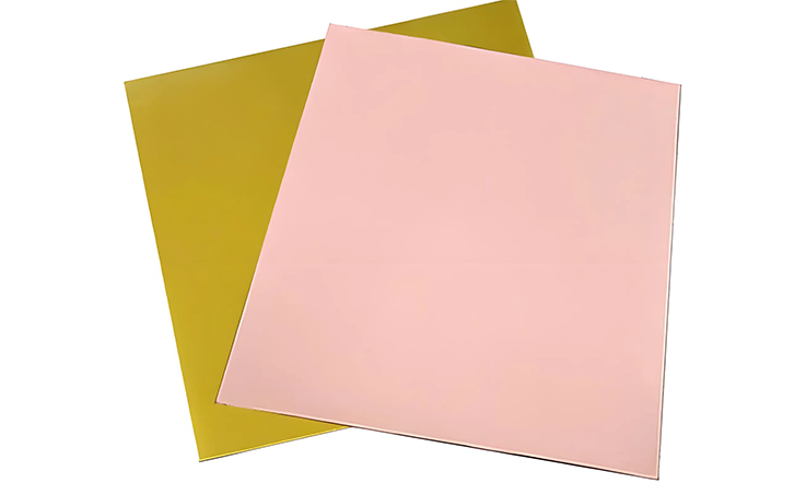
Glass-Reinforced Epoxy Resin Structure in ISOLA IS420 PCB Laminates
ISOLA IS420 PCB uses an advanced E-glass fabric reinforcement system embedded in a proprietary epoxy matrix. While that may sound like textbook laminate tech, the results speak for themselves in fabrication environments. The weave itself is carefully selected for dimensional stability, helping reduce misregistration in high-layer-count PCBs.
To put it in real numbers:
●Tg: >170°C (DSC)
●CTE Z-axis (50–260°C): ~2.9%
●Peel Strength: >1.0 N/mm (1 oz. copper)
These aren’t just lab figures. We’ve seen real-world stackups hold ±10% impedance across 14 layers with no skew failures over multiple reflow cycles. If your designs are pushing HDI boundaries, or involve staggered via transitions, this stable fabric-resin blend lets your signals stay within tolerances — without constant material debugging.
Resin System Performance under Thermal and Electrical Stress
High-Tg is just the tip of the iceberg. IS420’s epoxy resin system isn’t just tough under heat — it’s consistent under electrical load, too. For teams juggling high-speed SERDES and differential pair isolation, the Df value at 1 GHz sits near 0.0161, which helps suppress signal attenuation across longer interconnect paths.
Let’s break it down:
| Property | Value | Test Method |
| Dielectric Constant (Dk) @ 1GHz | ~4.17 | IPC-TM-650 2.5.5.5 |
| Dissipation Factor (Df) @ 1GHz | ~0.0161 | IPC-TM-650 2.5.5.5 |
| Thermal Stress (288°C, solder float) | >10 seconds | IPC-TM-650 2.4.24.1 |
So what does this mean for your boards? For one, signal integrity doesn’t tank when you’re routing longer runs or doubling back on differential traces. Second, thermal cycles — even aggressive reflows — don’t push the resin into a phase where outgassing, delamination, or micro-cracks start forming.
If your boards see mission duty in elevated ambient environments or back-to-back reflows during assembly, this resin keeps its cool. And that saves your yield numbers from going south.
Compatibility of ISOLA IS420 PCB Materials with Advanced Prepregs
One of the underappreciated features of the ISOLA IS420 PCB system is how it plays nice with a variety of prepreg formats — especially 2116, 1080, and 7628 variants — which makes it plug-and-play for most high-speed backplanes and signal interconnect platforms.
Why does that matter?
●Better resin flow control during lamination = fewer voids in blind/buried via structures
●Smooth copper-to-resin transitions = improved pad stability during reflow
●Reduced glass-weave skew = tighter trace impedance control across parallel signal lanes
In other words: you can build high-density PCBs with microvia integration, fine-line etching, and staggered core stackups without switching out your entire lamination tooling or revisiting your prepreg vendors. That means faster NPI cycles, lower tooling costs, and fewer surprises during fab.
Electrical and Thermal Properties of ISOLA IS420 PCB Laminates
When building high-layer-count boards or performance-driven substrates, the choice of laminate sets the tone for signal behavior, thermal endurance, and fabrication consistency. ISOLA IS420 PCB materials are engineered to deliver electrical reliability and thermal stability without throwing curveballs during processing. Based on a high-Tg epoxy system with a thermal glass transition around 180°C by DSC, IS420 laminates come prepared for repeated lead-free reflows, laser drilling, and aggressive routing densities — and they don’t cave under pressure.
Thermal excursions, RF speeds, impedance control, and dielectric uniformity — these are everyday headaches for layout teams and manufacturing lines. And when your project’s on the clock, the last thing you want is a laminate flaking out in the reflow oven or bending your signal integrity out of shape. Let’s dig into what makes the electrical and thermal properties of ISOLA IS420 PCB materials reliable, layer after layer.
Controlled Dielectric Constant and Low Dissipation Factor in ISOLA IS420 PCB
Signal attenuation, phase delays, and differential pair mismatches don’t usually show up in the early prototypes — they rear their heads during volume builds or extended frequency sweeps. That’s why a consistent dielectric constant and low dissipation factor are non-negotiables for design teams pushing into multi-gigabit territory.
ISOLA IS420 PCB maintains a dielectric constant near 4.17 at 1 GHz, providing a stable propagation environment across traces, vias, and planes. What that means in practice? Less skew on high-speed pairs, better signal edge retention, and tighter impedance control — even when routed across multiple dielectric interfaces.
The dissipation factor sits around 0.0161 at the same frequency, which translates into lower signal losses and cleaner transmission lines over distance. For those managing timing budgets in DDR4 layouts or XAUI/PCIe designs, this adds headroom without needing exotic low-loss materials that break the bank or demand custom processing.
This isn’t theoretical fluff — in real boards, this dielectric predictability shows up in tighter eye diagrams and reduced tuning headaches. If you’ve ever watched a signal degrade because a material’s Dk floated between lots, IS420 brings a little calm to the chaos.
Thermal Decomposition (Tg 180°C) and T288 Endurance Characteristics
Let’s face it — soldering, lamination, rework, and reflow are all thermal stress tests. ISOLA IS420 PCB brings a Tg of 180°C by DSC, which is well above traditional FR-4 but remains process-friendly for standard lamination profiles.
Even more telling? Its T288 performance:
| Property | Value |
| Tg (DSC) | 180°C |
| Time to Delamination @ 288°C | >10 minutes |
| T260 (Time to Delam at 260°C) | >30 minutes |
| Thermal Stress (288°C, solder float) | Pass (Multiple cycles) |
That kind of staying power keeps your multilayer stackups stable during lead-free solder processes and repeated thermal exposure. Whether you’re assembling a 12-layer control board with embedded passives or a high-speed routing core, IS420 won’t flake out under oven temps.
Z-Axis CTE Behavior in Multilayer ISOLA IS420 PCB Stackups
Z-axis expansion is where multilayer reliability either stays locked down — or goes off the rails. Excessive expansion between 50°C and 260°C can stretch plated through-holes and create interconnect instability, especially across thick stackups with heavy copper or multiple prepreg layers.
Here’s how ISOLA IS420 PCB performs in the Z-axis:
| Property | Value | Measurement Range |
| CTE (Z-Axis) | ~2.9% | 50°C–260°C |
| T260 | >30 minutes | – |
| T288 | >10 minutes | – |
That Z-axis CTE behavior isn’t just a stat — it directly affects drill registration, via reliability, and the mechanical integrity of plated barrels under thermal cycling.
For instance, in a 14-layer board with stacked vias and ENIG finish, we ran thermal shock tests from -40°C to +130°C, 500 cycles. The IS420 boards held up with zero failures in microvia or plated barrel continuity. That’s not marketing fluff — it’s data logged under IPC-TM-650.
If you’re dealing with stacked or staggered vias, blind/buried transitions, or thick boards with 2 oz copper, the low Z-axis expansion here is a huge relief.
ISOLA IS420 PCB Signal Integrity Optimization in High-Speed Applications
When signal clarity is on the line, the laminate selection can influence the overall performance of high-speed multilayer boards. ISOLA IS420 PCB materials have gained traction among fabrication professionals tackling challenges like insertion loss, crosstalk, impedance mismatch, and unpredictable skew due to glass weave effects. These substrates combine a stable resin system with consistent electrical behavior—allowing our designers to fine-tune stackups for high-frequency layouts without second-guessing laminate behavior under stress. Let’s break it down further into specific characteristics that address real-world signal performance.
Insertion Loss and Crosstalk Reduction in ISOLA IS420 PCB Substrates
Electromagnetic noise and dielectric loss are common headaches for design teams chasing clean signal transmission at higher data rates. ISOLA IS420 laminates use a high-Tg epoxy resin with a refined glass weave structure, which supports loss minimization strategies in controlled impedance environments.
Key points:
●Low dielectric loss (Df ≤ 0.0161 at 1 GHz) helps preserve signal amplitude and waveform shape across long trace runs.
●Tight Dk (4.17 ± 0.05 at 1 GHz) enhances impedance matching, reducing unwanted reflections and signal degradation.
●Reinforced glass cloth architecture limits crosstalk between adjacent traces, helping maintain channel isolation in dense routing environments.
If you’re routing 10+ layer boards with mixed-signal requirements, this laminate gives you room to breathe without the signal bleed.
High-Frequency Impedance Control in ISOLA IS420 PCB Layouts
Precision impedance management is no longer optional—it’s baked into the layout process from day one. The IS420’s resin-glass consistency and dimensional stability under thermal cycles allow for predictable impedance profiles.
Key points:
●Low Z-axis CTE (~2.8% below Tg) helps prevent dielectric expansion under reflow, which preserves signal timing and impedance consistency.
●Compatible with fine-pitch BGA footprints and HDI routing, supporting edge rate-sensitive signals without impedance dips.
●Consistent prepreg flow and thickness enable stackup repeatability—an advantage for high-volume production and simulation accuracy.
Don’t leave impedance tuning to guesswork—start with a material that tracks with your signal speed.
Glass Weave Mitigation Techniques in ISOLA IS420 PCB Stackups
Designers know the story: skew shows up, eye diagrams collapse, and suddenly, the glass weave is under the microscope. ISOLA IS420’s tight-weave construction and prepreg pairings make it easier to counteract these effects without jumping through hoops.
Key points:
●Utilizes spread glass styles (e.g., 3313, 2116) that reduce the risk of skew-related signal distortion at gigabit rates.
●Supports weave rotation techniques for critical differential pairs—particularly valuable in 10Gbps+ backplane-style layouts.
●Reduces phase mismatch and timing delay between differential signals routed across fiber bundles, keeping margins intact.
If your design team is running parallel lanes at high speed, the material choice makes all the difference in reducing bit errors from the start.
High-Layer Count Multilayer Design with ISOLA IS420 PCB Materials
When working with dense PCB architectures—particularly those spanning 6 to 20 layers—material characteristics begin to shape routing logic, layer pairing, and lamination schedules. ISOLA IS420 substrates, with their stable resin matrix and consistent dielectric performance, are suited to support such builds without compromising dimensional accuracy or interconnect reliability.
In this section, we’ll walk through how these materials behave in real-world stackups, what to consider when selecting prepreg combinations, and how to manage resin flow during lamination. If you’re in the weeds with HDI planning or tight impedance demands, it’s worth dialing in every inch of detail here.
Stackup Planning from 6-Layer to 20-Layer ISOLA IS420 PCB Boards
Stackup definition in high-count ISOLA IS420 designs calls for a balance between performance consistency and manufacturability. Engineers dealing with impedance-sensitive routing or embedded component strategies often push for tight layer-to-layer control, where IS420’s thermal and electrical stability allows more predictable modeling during simulation.
●Predictable Z-axis behavior across thermal cycles helps maintain internal layer alignment.
●Tg of 180°C enables repeated lamination without early onset of delamination or dielectric breakdown.
●Uniform Dk performance across X, Y, and Z directions supports consistent signal behavior, especially for differential pair routing.
Prepreg Selection Strategy for Layer Isolation and Uniform Dielectrics
Choosing prepreg materials isn’t just about bond strength—it’s also about dielectric spacing, resin content, and flow behavior during the lam cycle. ISOLA’s 185HR or 370HR prepregs can be matched with IS420 cores depending on the thickness, Tg alignment, and thermal profile of your project.
| Prepreg Type | Resin Content (%) | Tg (°C) | Recommended for Copper Weight |
| 185HR | 43 | 180 | 1 oz |
| 370HR | 38 | 180 | 2 oz |
●Prepreg flow rate must align with copper weight and design density to prevent resin starvation or squeeze-out.
●Consistency in glass style between core and prepreg layers reduces microetch channeling at the interface.
●Void-free lamination is easier to achieve with compatible prepregs that share the resin system architecture.
Controlled Resin Flow and Registration for High-Density ISOLA IS420 PCB Design
High-density interconnects rely on resin flow that’s just enough—but not too much. With ISOLA IS420, resin control becomes easier due to its engineered flow characteristics under pressure and temperature. Controlled lamination profiles let you get away with tighter via-in-pad tolerances and consistent dielectric uniformity across the panel.
| Parameter | IS420 Value | Impact on HDI Design |
| Z-axis Expansion | <2.8% | Supports fine pitch |
| Lamination Pressure | 300–400 psi | Improved resin flow |
| Lamination Temperature | 190–210°C | Stable Tg behavior |
| Via Drill Smear | Minimal | Cleaner holes |
●Reduced Z-axis expansion supports tighter annular ring design and prevents pad lift in laser-drilled vias.
●Optimized lamination curve for IS420 can limit resin bleed while still allowing good wet-out on copper.
●Improved drill quality and reduced smear come from consistent Tg and Dk matching across layers.
PCB Manufacturing Guidelines for ISOLA IS420 PCB Fabrication
When processing ISOLA IS420 laminates, your fabrication line doesn’t require unconventional tricks—but it does demand tight process control, a solid understanding of laminate behavior, and a no-shortcuts approach to thermal cycles and interconnect integrity. IS420’s high-Tg epoxy formulation integrates well with modern lead-free assembly and HDI stackups, but every stage from lamination to plating must be precisely managed. Let’s break down how to run this material like a pro and avoid the usual pitfalls.
Lamination Profile and Temperature Control for ISOLA IS420 PCB
To get consistent bond quality and layer adhesion using ISOLA IS420, thermal management during lamination can’t be an afterthought. Here’s what experienced techs track in production:
Pre-bake Guidelines-
●Bake core and prepreg at 125°C for 4–6 hours to drive off residual volatiles
●Avoid overbake—too long and you’ll degrade flow and resin wet-out
Press Cycle Optimization-
●Preheat ramp: 2.5°C–3.0°C/sec to 150°C, then apply pressure
●Cure plateau: Hold at 190°C–200°C for 60–90 minutes
●Cooling: Controlled descent under pressure to prevent resin shift
Pressure Profiling-
●Initial low-pressure contact to avoid resin squeeze-out
●Gradual increase to 180–250 psi, tailored by layer count and copper weight
Drilling, Hole Wall Integrity, and De-Smear Best Practices
ISOLA IS420 has a robust epoxy-glass matrix, but improper drill settings will still tear it up like a kid in a candy store. Here’s how to keep barrel walls intact and resin smear at bay:
Drilling Parameters for Rigid Cores-
●Entry/exit materials: Use aluminum and white film stackups
●Drill speed: 150–180 SFM for 0.25–0.30mm drills
●Peck drilling for >12:1 aspect ratio holes
Desmear Chemistry-
●Plasma cleaning with CF₄/O₂ mix (standard prep)
●For high-layer boards, alkaline permanganate may be added—test first
Hole Wall Cleanliness Check-
●Cross-section at least 5–10 holes per panel lot
●Look for resin smear, micro-cracks, and inner layer voiding
Via Filling, Copper Plating, and Lead-Free Reflow Compatibility with ISOLA IS420 PCB
As OEMs push denser designs, via filling and plating uniformity become need. ISOLA IS420 handles stacked vias and lead-free reflow without flinching—if process steps are dialed in tight.
Conductive Via Fill Strategies-
●Vacuum-assisted fill for buried and stacked microvias
●Use compatible via-fill pastes that won’t outgas under reflow
●Cure schedule: ramp to 150°C over 30 mins, then dwell at 180°C for 1 hour
Copper Plating for Through-Hole and Microvias-
●DC + periodic reverse current boosts uniformity
●Additives tuned for grain structure and throwing power
●Target copper thickness: 25–30µm in via walls
Lead-Free Assembly Validation-
●IS420 can withstand SAC305 profiles up to 260°C without measurably shifting Tg
●Test T260 and T288 on real stackups, not just datasheets
ISOLA IS420 PCB Use in High-Performance Medical and Communication Systems
ISOLA IS420 laminate systems are widely deployed in the fabrication of high-layer-count PCBs used in advanced medical diagnostic units and communication infrastructure. These applications require consistent dielectric behavior, resistance to thermal and environmental cycling, and moisture stability over extended product life cycles. IS420 is designed to maintain consistent electrical and mechanical performance metrics within these scenarios, where component reliability must remain predictable under varied operating loads. The following sections detail core considerations tied to electrical stability, material performance under stress, and moisture exposure.
Electrical Stability for Data-Driven Medical ISOLA IS420 PCB Applications
Applications such as MRI control units, electrophysiology interfaces, and wearable health monitoring modules demand a stable signal environment with low dielectric variability. IS420’s consistent dielectric properties help maintain signal timing and prevent skew across high-speed differential pairs.
●Dielectric constant (Dk) stability is maintained across frequency and temperature, minimizing timing shifts.
●Low dissipation factor (Df) values allow accurate signal propagation in analog sensor chains and digital transceivers.
●Predictable impedance profiles across multilayer stackups improve calibration consistency in sensing applications.
In multi-channel acquisition systems, impedance mismatches can introduce waveform distortion. IS420’s controlled dielectric behavior supports stable waveforms without requiring complex impedance tuning across adjacent layers.
Reliability Under Environmental Load in ISOLA IS420 PCB for Communication Equipment
Communication-grade PCBs assembled with IS420 are subject to stress factors including temperature cycling, humidity exposure, and mechanical vibration. The laminate system’s physical stability and bonding integrity contribute to signal retention and interconnection durability.
●Tg at 180°C offers resistance to thermomechanical stress during wave soldering and lead-free reflow.
●T288 values exceeding 10 minutes support delamination control during multiple soldering cycles.
●Low Z-axis CTE values help manage via integrity across backplane and multilayer communication boards.
| Parameter | IS420 Typical Value | Application Relevance |
| Glass Transition Temperature (Tg) | 180°C | Withstands multiple solder reflow cycles |
| T288 (Time to Delamination) | >10 minutes | Stability during lead-free assembly |
| Z-axis CTE (50°C–260°C) | <45 ppm/°C | Maintains via structure under thermal cycles |
| Peel Strength (1 oz Cu) | >7 lb/in | Sustains interconnect adhesion after rework |
This thermal endurance allows repeatable board behavior during rework cycles in field-deployed switching units and signal processors. For PCB manufacturers aiming at high production consistency, IS420 offers stability across large panel sizes with minimal resin movement or delamination risk.
Moisture Resistance and Aging Control in ISOLA IS420 PCB Circuits
Enclosures for both medical and communication assemblies can be exposed to ambient moisture levels over long periods. ISOLA IS420 is engineered with low moisture absorption and thermal reliability, helping maintain predictable electrical performance after aging or environmental stress.
●Moisture absorption rates are below 0.2%, aiding dielectric reliability in humid environments.
●CAF resistance supports long-term interconnect reliability under DC bias and humidity exposure.
●Resin system aging shows minimal shift in Dk/Df characteristics even after thermal-humidity cycling.
| Characteristic | IS420 Value | Use Case Benefit |
| Moisture Absorption (24hr @ 50°C, 93% RH) | <0.2% | Ensures dielectric stability in humid installations |
| CAF Resistance | High | Reduces risk of conductive filament formation |
| Post-Aging Dk Drift (ΔDk) | <0.05 | Maintains predictable signal performance over years |
| Thermal Cycling Resistance | Excellent | Withstands ≥1000 cycles from -40°C to 125°C |
This moisture and thermal resilience contributes to stable operation in PCB applications like remote telemetry modules, in-hospital patient data interfaces, and outdoor signal routing equipment. No protective overcoating or potting is needed to maintain dielectric consistency in most configurations.
ISOLA IS420 PCB vs Tuc, Nanya, Nelco, Panasonic, ITEQ and Other Epoxy-Based Laminates
When comparing high-performance epoxy-based laminates used in multilayer PCB designs, ISOLA IS420 often enters the conversation alongside brands like Tuc, Nanya, Nelco, Panasonic, and ITEQ. Each material platform presents unique electrical, thermal, and mechanical properties that impact PCB stackup reliability, signal transmission, and manufacturing compatibility. For design professionals aiming to specify a material that meets high-frequency, high-layer-count, or thermally demanding applications, these differences merit a closer look.
Tg, Dk, Df, and Thermal Expansion Comparison Across PCB Materials
Thermal and electrical behavior directly influences how well a substrate handles high-frequency signaling and elevated reflow processes. ISOLA IS420 maintains a Tg of 180°C with a Dk near 4.17 and Df around 0.0161 at 1GHz. This provides measurable stability for applications requiring consistent impedance and reduced loss across multiple signal layers.
●ISOLA IS420
– Tg: 180°C (DSC)
– Dk: 4.17 @ 1GHz
– Df: 0.0161 @ 1GHz
– Z-axis CTE: ~60 ppm/°C below Tg
●TUC TU-768 / TU-872 SLK
– Tg range: 170–180°C
– Dk: 4.4–4.3
– Df: 0.018–0.019
– Lower Z-CTE for laser via compatibility
●Nanya NP175TL / NP180
– Tg: 175–180°C
– Dk: 3.8-4.0
– Df: 0.012–0.014
– Reliable through-hole plating under reflow cycles
●Nelco N4000-13EP SI
– Tg: 180–185°C
– Dk: 3.8–4.2
– Df: 0.009–0.014
– Low X-Y expansion under lead-free thermal load
●Panasonic Megtron 6 / R-1755
– Tg: 185°C
– Dk: 3.45–3.7
– Df: 0.002–0.005
– Notably low-loss for RF and SI-sensitive work
●ITEQ IT-180A / IT-968 / IT-988G SE
– Tg: 175–200°C
– Dk: 3.6–4.4
– Df: 0.015–0.016
– Glass weave control in high-speed platforms
Each material sits within specific thermal expansion tolerances and dielectric profiles. These parameters affect layer registration, via stability, and impedance alignment in stackups operating above 1GHz. Selecting based on actual Dk/Df performance across the bandwidth range (not just 1GHz) gives better visibility into long-trace losses.
Performance Gains with ISOLA IS420 PCB in Multilayer Stackups
While many mid-loss to low-loss resins are on the table, ISOLA IS420 brings manufacturing familiarity and processing stability to high-layer-count builds. For OEMs working in 10 to 24-layer structures with via-in-pad or staggered microvias, predictable resin flow and thermal endurance simplify fabrication.
●Glass-reinforced core with low Z-axis expansion ensures plated through-hole integrity during lead-free assembly.
●Resin content tunability supports precise control of dielectric spacing, which facilitates achieving 50Ω or 100Ω impedance targets.
●Compatible with standard lamination cycles—IS420 does not require exotic press profiles, which saves costs for mid-volume builds.
In stacked via arrays or backdrilled configurations, IS420 maintains drill-to-copper spacing and resin coverage without microcracking, making it suitable for hybrid structures combining digital control and analog signals on the same board.
Application-Specific Tradeoffs Between ISOLA IS420 PCB and Other Epoxy-Based Laminates
Choosing ISOLA IS420 over materials like Megtron 6 or ITEQ IT-988G SE often involves performance versus cost or process compatibility considerations. While IS420 offers excellent electrical and thermal consistency, it may not match ultra-low Df laminates where insertion loss margins are minimal.
●ISOLA IS420 vs Panasonic Megtron 6: Megtron 6 has a much lower Df (0.004), but its higher price and specialized processing make IS420 preferable for mid-speed mixed-signal work under 10GHz.
●ISOLA IS420 vs ITEQ IT-988G SE: ITEQ’s advanced resin system offers lower Df (0.0013), but IS420 provides more predictable drilling and laser via registration in high-density outer layers.
●ISOLA IS420 vs Nelco N4000-13EP SI: Nelco products offer good CAF resistance and reliable plating in lead-free cycles, comparable to IS420, though ISOLA’s widespread availability gives fabricators more sourcing options.
The decision comes down to electrical frequency targets, copper layer count, via architecture, and allowable budget. In many 8–20 layer PCB boards, IS420 balances manufacturing yield with predictable signal loss, especially where high-speed differential pairs are short or isolated.
Design for Manufacturability Using ISOLA IS420 PCB Materials
Fabricating multilayer PCBs with ISOLA IS420 requires attention to process-specific constraints that influence both cost and yield. The material’s thermal and mechanical behavior across lamination, drilling, and final assembly stages has direct impact on manufacturability, especially in dense layer-count configurations. In this section, we explore layout, stackup, and material behavior strategies that allow for higher precision, fewer process corrections, and more predictable outputs when using IS420 in volume manufacturing.
Drill-to-Copper Clearance and Pad Registration in ISOLA IS420 PCB Layout
Maintaining accurate drill-to-copper clearances and aligning pad registrations is not only about compliance with IPC Class 2 or 3—it determines whether downstream processes hold up under scrutiny in volume builds.
●IS420 features a CTE-z of approximately 2.8% between 50–260°C, which provides more stable hole-wall alignment during reflow and lamination cycles.
●Designers can target minimum 8 mil annular rings on 0.25 mm pads when drill tolerances are held to ±2 mils, enabling tighter vias without compromising fabrication tolerance.
●Hole-to-copper clearances down to 8 mils are feasible on 1 oz copper layers using laser direct imaging (LDI) in combination with mechanical X-ray registration.
Example: A 12-layer design for a data acquisition system using 0.1 mm laser vias and 0.18 mm pads achieved 98% first-pass yield using IS420 when drill alignment was tuned using automatic optical inspection feedback loops.
Layer Symmetry and Warpage Control in ISOLA IS420 PCB Stackups
Lamination distortion, bow, and twist aren’t just cosmetic—they affect assembly registration, automated optical inspection, and even socket engagement.
●IS420’s dimensional stability (≤ 0.05%) helps support stackup symmetry, especially in 8–16 layer boards using mixed signal routing.
●Balanced copper usage on outer layers and mirrored prepreg selections reduce Z-axis movement during cooldown, minimizing layer shift.
●Material movement in IS420 under heat stress (post-lam and pre-routing) averages under 0.2%, based on vacuum lamination cycles of 180–185°C peak.
| Stackup Configuration | Warpage After Lamination | Notes |
| Symmetric 8-layer | <0.5 mm | IS420 + symmetrical copper |
| 10-layer hybrid stack | 0.6–0.8 mm | IS420 + asymmetric RF zones |
| 14-layer data stack | <0.4 mm | IS420 with identical top/bottom plane weight |
Resin Voids, CAF Resistance, and Material Reliability Factors
Conductive anodic filamentation (CAF), voiding, and delamination concerns can sideline even the best PCB designs. IS420’s resin system is formulated to reduce such risks under demanding process and field environments.
●CAF resistance of IS420 exceeds 500 hours in standard IPC TM-650 testing under 85°C/85% RH bias conditions.
●Resin-glass adhesion remains intact after multiple simulated reflow cycles up to 260°C, especially with 1080 and 2116 glass styles.
●Vacuum-assisted lamination reduces the risk of prepreg voids between 0.5%–1.0%, with IS420’s flow window offering consistent coverage over dense via fields.
| Parameter | ISOLA IS420 | Typical Mid-Grade Epoxy Laminate |
| CAF Resistance (85/85) | >500 hours | <300 hours |
| Voiding Risk (after press) | <1.0% | 1.8–2.5% |
| Resin-Glass Peel Strength | 1.1 N/mm | 0.7–0.9 N/mm |
Prototyping and Production Workflow with ISOLA IS420 PCB Substrates
Transitioning from design concept to volume production using ISOLA IS420 laminates requires a systematic approach aligned with the material’s thermal, mechanical, and electrical properties. This section outlines how to navigate early-stage planning, test verification, and production scaling without compromising process reliability or consistency.
BOM Planning and Pre-Stackup Simulation for ISOLA IS420 PCB
A well-prepared Bill of Materials (BOM) and early simulation of the PCB stackup set the stage for efficient development. ISOLA IS420, with its Tg of 180°C and low dissipation factor, demands precise coordination between material characteristics and electrical design constraints.
Key considerations include:
●Material Compatibility: Selecting prepreg and core combinations that support the intended impedance values and thermal expansion limits helps avoid delamination and signal distortion.
●Simulation Precision: Early use of field solver tools to model multilayer configurations ensures design tolerances are respected, particularly in high-layer-count boards.
●Thermal Behavior Review: Aligning soldering profiles and reflow parameters with the IS420 thermal profile reduces risk during assembly.
Some Design teams often model a 10 or 12-layer construction with alternating signal, ground, and power planes to fine-tune the impedance characteristics in pre-layout stages. Careful planning here reduces rework and keeps prototype cycles shorter.
Test Coupon Design for Electrical Verification in ISOLA IS420 PCB
Test coupons are integrated into production panels to allow direct measurement of electrical properties post-fabrication. For ISOLA IS420-based designs, they offer a way to validate theoretical design assumptions through physical verification.
Design teams should:
●Include both differential and single-ended transmission lines for impedance checks.
●Design daisy-chain structures that simulate actual routing to measure continuity and open faults.
●Use isolation structures to confirm the dielectric strength between neighboring conductors.
These structures help ensure that the fabricated board performs according to modeled expectations. For example, if your design targets 100-ohm differential impedance, verification through these coupons gives a direct pass/fail outcome before the boards reach assembly.
Transitioning from Prototype to Mass Production with ISOLA IS420 PCB Boards
Scaling from small-batch prototyping to full-scale production involves adapting several process parameters. ISOLA IS420’s resin system and mechanical stability support such a transition, but manufacturing conditions must still be closely controlled to avoid defects and variability.
Consider the following steps:
●Adjust Process Settings: Lamination pressure, drilling feed rates, and exposure times may need tuning to accommodate larger panels and higher throughput.
●Process Validation: Using control charts and yield tracking allows for identification of any trend shifts as production scales.
●Material Consistency: Coordinate with your material supplier to secure uniform prepreg and core batches. Any variation can affect drilling quality, plating consistency, or impedance control.
For instance, a prototyping line might run at lower lamination pressure to evaluate board behavior, while mass production lines require higher, more consistent pressure to avoid resin starvation and warpage in high-layer-count constructions.
Why Choose Us as Your ISOLA IS420 PCB Manufacturer?
Working with ISOLA IS420 materials requires not only technical capability but also precise coordination across stackup planning, fabrication, and customer-specific requirements. From the initial quote to production ramp-up, we provide support with high attention to engineering integrity, laminate behavior, and design-for-manufacturability alignment.
Below, we outline how we help customers integrate ISOLA IS420 substrates into functional, high-reliability PCB designs—backed by material familiarity, process tuning, and data-driven insights.
Requesting a Quote or Technical Support for ISOLA IS420 PCB Projects
When you’re working on tight deadlines or high-performance builds, having a partner who responds quickly and accurately can streamline your development timeline. We support:
●Fast-response quoting based on detailed layer counts and board specifications
●Material lead time validation for ISOLA IS420 stock
●Engineering clarification for design impedance, stackup balance, and prepreg usage
●CAM team support on impedance planning, via modeling, and signal integrity guidance
Reach out with your project specs—we’re ready to assist and clarify every step before production begins.
Data Requirements and Design Files for ISOLA IS420 PCB Quotation
Precision quoting for ISOLA IS420 depends on well-prepared documentation. We suggest submitting:
●Gerber files or ODB++ with layer sequence clearly defined
●IPC-2581 stackup or layer detail showing dielectric thicknesses and copper weights
●Controlled impedance targets and materials notes
●Via structure references (through-hole, blind/buried, or via-in-pad)
If you’re still refining your layout, we can support with DFM checks ahead of quote submission. Send your draft files to begin early-stage alignment.
Stackup Review and Engineering Feedback on ISOLA IS420 PCB
ISOLA IS420’s low Dk and mid-range Tg profile support a range of applications, but stackup design influences everything from resin flow to copper balance. We offer:
●Material usage mapping for each layer and dielectric interface
●Review of core/prepreg pairing to avoid delamination or z-axis stress
●Registration control advice for high-layer count builds
●DRC and netlist cross-checking prior to tooling approval
Share your stackup proposal with us—we’ll help fine-tune it with our IS420 build experience.
Evaluation Samples and Process Consultation for ISOLA IS420 PCB
Before entering production, many customers request evaluation runs or consultation. We can:
●Provide small-batch trial builds with ISOLA IS420 for signal testing or mechanical validation
●Assist with thermal aging, solder reflow, and CAF resistance test planning
●Offer panel utilization strategies to optimize yield
●Discuss prepreg fill guidance for via structures and cavity boards
Let’s walk through your prototype goals—early collaboration helps set the tone for dependable production.
FAQs About ISOLA IS420 PCB
1.What is the standard prepreg style available for ISOLA IS420?
ISOLA IS420 typically uses 106, 1080, 2116, and 7628 prepreg glass styles.
2.Can ISOLA IS420 be used with HDI PCB designs?
Yes, IS420 supports HDI structures including microvias and sequential lamination.
3.What is the recommended copper thickness for signal layers on ISOLA IS420?
Common builds use 0.5 oz or 1 oz copper for signal integrity control.
4.Is ISOLA IS420 compatible with rigid-flex PCB constructions?
IS420 can be used in rigid sections of rigid-flex designs but is not flexible itself.
5.What is the maximum layer count typically supported using ISOLA IS420?
It is frequently used in builds up to 20+ layers, depending on stackup design.
6.Are there halogen-free versions of ISOLA IS420 available?
ISOLA IS420 is a standard halogenated epoxy; halogen-free versions are not part of this series.
7.How does ISOLA IS420 behave under multiple reflow cycles?
It maintains dimensional and thermal stability under 3x or more lead-free reflow cycles.