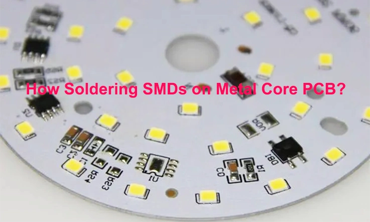
Soldering surface-mount devices (SMDs) on metal core PCBs requires careful attention to detail and adherence to specific techniques. Metal core PCBs offer excellent thermal conductivity and heat dissipation, making them ideal for applications with high power or thermal requirements. This article serves as a comprehensive guide to effectively soldering SMDs on metal core PCBs, outlining the necessary steps and considerations for achieving reliable solder joints. From preparation to inspection, understanding the process will ensure successful assembly and enhance the overall performance of electronic devices.
Significance of Metal Core PCBs
Metal core PCBs (MCPCBs) are a specialized type of printed circuit board that leverage the advantages of a metal base layer, typically aluminum or copper, bonded to a traditional FR4 or polyimide dielectric layer. This distinctive construction provides several notable benefits over standard PCBs:
1. Improved Thermal Regulation; Metal Core Printed Circuit Boards (MCPCBs) are highly effective, at dispersing heat because of the conductivity of the metal base layer. This remarkable ability to dissipate heat makes them well suited for tasks that produce heat, like power electronics, LED lighting and high performance computing.
2. Improved Electrical Performance: The metal base layer in MCPCBs offers a low-impedance pathway for electrical signals, resulting in reduced signal loss and superior overall electrical performance. This advantage proves particularly valuable in high-frequency applications and circuits with stringent signal integrity requirements.
3. Increased Mechanical Strength and Durability: MCPCBs exhibit greater robustness and durability compared to standard PCBs, thanks to the rigid metal base layer. They can withstand higher mechanical stresses, vibrations, and shock, making them suitable for demanding environments and rugged applications.
4. Reduced Size and Weight: By utilizing a metal base layer, MCPCBs can achieve a thinner and lighter profile while maintaining optimal performance. This aspect is particularly advantageous in applications where space and weight are critical considerations, such as aerospace and portable electronics.
5. Cost-Effectiveness: In high-volume production scenarios, MCPCBs can offer cost advantages over standard PCBs. The thinner profile and simplified design contribute to reduced material and manufacturing costs, making them an economically viable option.
Metal core PCBs offer a mix of thermal control improved electrical efficiency, enhanced mechanical durability and affordability. These attributes make them options, for a range of uses, in different industries.
Advantages and Challenges of Soldering SMDs on Metal Core PCBs
Advantages of Soldering SMDs on Metal Core PCBs:
1. Enhanced Heat Dispersion; The metal core layer, within metal core PCBs helps in dissipating heat from the SMDs. This proves advantageous, for high power SMDs or situations where managing heat is crucial.
2.Improved Electrical Functionality: Metal core PCBs offer a low-impedance path, for signals reducing signal loss and enhancing overall electrical performance. This benefit is especially beneficial, for high frequency circuits and applications that demand signal integrity.
3. Increased Mechanical Strength: Metal core PCBs provide strength and durability when compared to standard PCBs. They show resistance to bending, warping and vibration making them ideal, for use, in demanding environments.
4. Reduced Size and Weight: The utilization of a metal core layer enables thinner and lighter PCB designs. This is advantageous for applications where space is limited or weight reduction is a priority, such as portable devices.
Challenges of Soldering SMDs on Metal Core PCBs:
1. Temperature Regulation; Controlling the soldering temperature can pose a challenge because of the conductivity of the metal core. Maintaining the temperature is essential to prevent any harm to both the SMDs and the PCB.
2. Solder Bridging: The close proximity of SMDs on metal core PCBs increases the risk of solder bridging between adjacent pads. Careful attention to solder paste application and reflow profiling is necessary to prevent this issue.
3. Voiding: The presence of the metal core can impede solder penetration and result in voids within the solder joints. Voids can weaken the joints and compromise their reliability, requiring careful process optimization.
4. Flux Selection: The selection of suitable flux is important to ensure compatibility with the metal core material and minimize the formation of intermetallic compounds (IMCs) during soldering.
5. Equipment Requirements: Achieving optimal soldering results on metal core PCBs may require specialized soldering equipment, such as high-power soldering irons or reflow ovens with precise temperature control.
Overall, soldering SMDs on metal core PCBs offers significant advantages, but it requires careful attention to temperature control, solder paste application, flux selection, and equipment considerations. By addressing these challenges, reliable and high-performance solder joints can be achieved on metal core PCBs.
Selecting the Right Soldering Technique for SMDs on Metal Core PCBs
The selection of a soldering technique for SMDs on metal core PCBs relies on various factors, including SMD size, quantity, desired precision, and available resources. Here are the primary soldering techniques commonly used for metal core PCBs:
1. Hand Soldering:
●Suitable for small-scale production and prototyping.
●Requires skilled operators and specialized tools.
●Provides good control over solder placement and temperature.
●Time-consuming for large quantities of SMDs.
2. Reflow Soldering:
●Ideal for mass production.
●Involves a reflow oven to melt the solder paste.
●Ensures consistent and repeatable soldering results.
●Requires careful temperature profiling to prevent thermal damage.
3. Wave Soldering:
●Suitable for high-volume production.
●Involves applying solder paste to the PCB and passing it over a molten solder wave.
●Efficient and cost-effective for large batches of PCBs.
●May not be suitable for complex PCB designs or SMDs with fine pitch.
4. Laser Soldering:
●Used for precise soldering of small or delicate SMDs.
●Utilizes a focused laser beam to melt the solder.
●Offers precise control and minimal thermal impact.
●Can be costly and requires specialized equipment.
Factors to Consider When Selecting a Soldering Technique:
●SMD Size and Pitch: Smaller SMDs and components with fine pitch require more precise soldering techniques, such as laser soldering or reflow soldering with fine-tuned temperature profiles.
●Quantity of SMDs: Hand soldering is suitable for small quantities, while reflow soldering or wave soldering is more efficient for mass production.
●Desired Precision: Applications demanding high precision benefit from laser soldering or reflow soldering with precise temperature control.
●Available Resources: The availability of specialized soldering equipment and skilled operators may influence the choice of soldering technique.
By carefully considering these factors, manufacturers can select the most appropriate soldering technique to achieve reliable and high-quality solder joints on metal core PCBs.
Preparing the Metal Core PCB for Soldering
Proper preparation of the metal core PCB is essential for achieving successful soldering of SMDs. The following key steps should be followed:
1. Cleaning:
●Thoroughly eliminate any contaminants, such as oils, dirt, or flux residue, from the surface of the metal core PCB using an appropriate cleaning agent.
●Gently scrub the surface using a lint-free cloth or brush.
●Ensure the PCB is completely dry before proceeding to the next steps.
2. Surface Activation:
●Apply a thin layer of flux to the metal core surface.
●The flux aids in removing any remaining oxides and promotes solder wetting.
●Select a flux that is compatible with both the metal core material and the solder paste being used.
3. Solder Paste Application:
●Apply solder paste to the SMD pads using a stencil or dispenser.
●Ensure the solder paste is evenly distributed and has the correct volume.
●Choose a solder paste specifically formulated for metal core PCBs, considering the desired melting point and viscosity.
4. Preheating:
●Preheat the PCB to a temperature slightly below the melting point of the solder paste.
●Preheating activates the flux and enhances solderability.
●Utilize a hot plate or convection oven for the preheating process.
5. Alignment and Placement:
●Precisely align the SMDs on the solder paste pads using a pick-and-place machine or manual placement tools.
●Ensure the SMDs are correctly seated without any solder bridges or shorts.
6. Tacking:
●Apply a small amount of solder to one or two pins of each SMD to tack them in place.
●Tacking prevents the SMDs from shifting during the subsequent reflow soldering process.
By meticulously following these preparation steps, the metal core PCB will be properly primed for soldering, resulting in excellent solderability, strong joints, and overall reliability.
Soldering Process for SMDs on Metal Core PCBs
Once the metal core PCB has undergone proper preparation, the soldering process can commence. The following key steps outline the soldering process:
1. Reflow Soldering:
●Place the prepared PCB in a reflow oven.
●The oven will subject the PCB to a controlled temperature profile, causing the solder paste to melt and form solder joints between the SMDs and PCB pads.
●Ensure precise temperature control to prevent any thermal damage to the SMDs or PCB.
2. Wave Soldering:
●Guide the PCB over a molten solder wave.
●The solder wave will flow over the PCB, creating solder joints between the SMDs and PCB pads.
●Ensure the solder wave is at the appropriate temperature, and align the PCB correctly to avoid solder bridging or shorts.
3. Hand Soldering:
●Use an iron to melt solder and create connections, between the SMDs and PCB pads.
●Position the tip of the iron at a 45 degree angle, to the PCB and add solder to the connection point.
● Monitor and control the temperature carefully to avoid overheating either the SMDs or PCB.
4. Inspection and Rework:
●Thoroughly inspect the soldered joints visually and electrically to ensure their proper formation and functionality.
●Address any defective solder joints through rework, which involves removing the old solder and re-soldering the SMD to rectify any issues.
5. Cleaning:
●Clean the soldered PCB to eliminate any flux residue or contaminants.
●Employ an appropriate cleaning agent, along with a soft brush or cloth, to ensure a thorough
cleaning process.
●Ensure the PCB is completely dry before further handling or testing.
By adhering to these soldering steps and employing suitable techniques and equipment, manufacturers can achieve high-quality and reliable solder joints on metal core PCBs.
Post-Soldering Inspection and Testing
After finishing the task it is crucial to conduct an examination and testing to guarantee the quality and dependability of the soldered connections, on metal core PCBs. The subsequent essential measures detail the inspection and testing procedures;
1. Visual Inspection:
Employ a microscope or magnifying glass to meticulously examine the solder joints for potential defects, including:
●Solder bridges
●Solder voids
●Incomplete solder joints
●Misaligned components
2. Electrical Testing:
Conduct comprehensive electrical tests to verify the functionality of the soldered joints and the overall PCB. Utilize multimeters or other appropriate test equipment to assess continuity, shorts, and proper signal transmission.
3. Automated Optical Inspection (AOI):
Use AOI machines to check the solder joints for any issues. AOI systems utilize cameras and image processing algorithms to identify and categorize anomalies, in the solder joints.
4. X-ray Inspection:
Utilize X-ray imaging to inspect the solder joints for internal defects such as:
●Voids
●Cracks
●Delamination
5. Thermal Cycling Test:
Expose the printed circuit board (PCB) to repeated rounds of temperature changes to assess the durability of the solder connections. Thermal cycling can uncover flaws or imperfections, in the solder joints that might go unnoticed, during usage.
6. Vibration and Shock Test:
To evaluate the durability of the solder connections subject the PCB to controlled vibrations and shocks. These procedures help pinpoint solder joints that could potentially crack or fail when exposed to stress.
By diligently conducting these inspection and testing procedures after soldering, manufacturers can ensure that the soldered joints on metal core PCBs meet the desired standards of quality and reliability.
Conclusion
Proper soldering techniques are crucial when working with SMDs on metal core PCBs. The careful preparation of the PCB surface, appropriate flux selection, precise solder paste application, and controlled heating during reflow are essential factors for achieving reliable solder joints. Thorough inspection and testing, including visual examination, electrical tests, AOI, X-ray inspection, and reliability testing, further ensure the quality and reliability of the soldered joints. By following the guidelines outlined in this article, manufacturers can confidently solder SMDs on metal core PCBs, resulting in robust and high-performance electronic assemblies. Mastering this process will contribute to the successful realization of advanced electronic devices across various industries.
Our services
Metal Core PCB Manufacturing & Assembly

