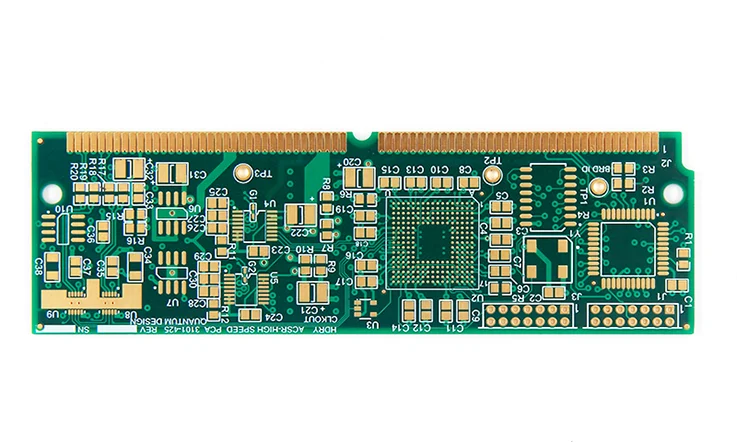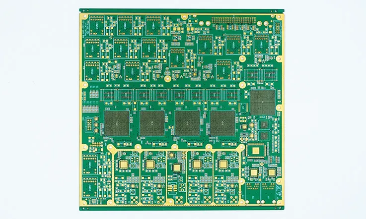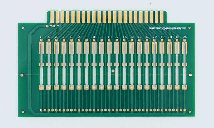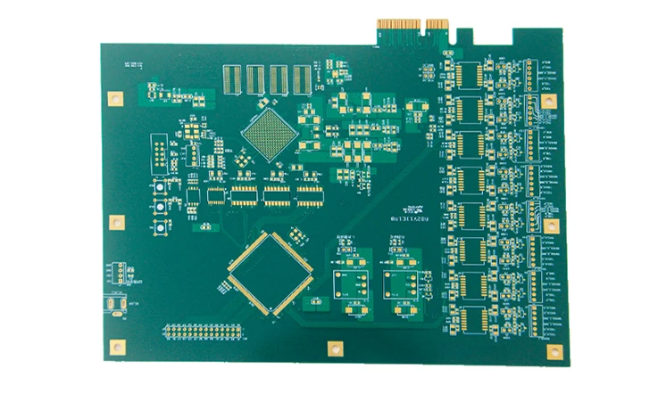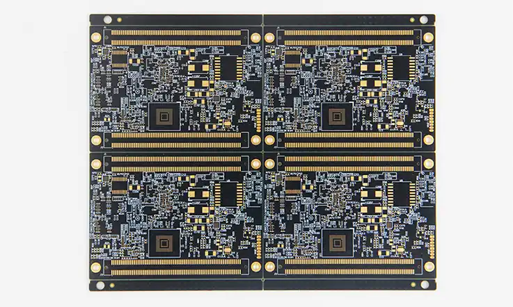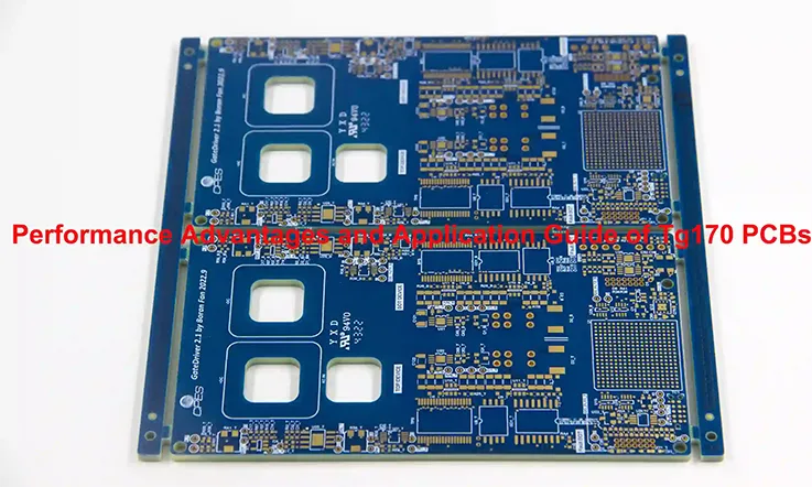
As electronic devices continue to evolve at an astonishing pace, the demand for high-performance printed circuit boards (PCBs) has never been greater. With industries like automotive, aerospace, and telecommunications pushing the boundaries of what’s possible, the need for durable, reliable, and thermally stable materials has become crucial. High Tg170 PCBs meet these growing demands, offering a well-balanced solution for applications that require superior thermal management and chemical stability. But what exactly sets Tg170 PCBs apart? This guide takes a deep dive into their unique properties, key benefits, and the real-world scenarios where they excel.
What is Tg170 in PCBs and Why Does It Matter?
Understanding Tg: The Glass Transition Temperature in PCBs
When we talk about Tg in the context of PCBs, we’re referring to the Glass Transition Temperature—the point at which a PCB material shifts from a rigid, glassy state to a softer, more elastic one. For standard FR4 materials, this transition happens around 130°C, which is often adequate for general-purpose electronics. However, when operating in high-temperature environments, standard FR4 can become unreliable, leading to structural issues such as delamination or warping.
High Tg170 materials are engineered to withstand these elevated conditions, withstanding temperatures up to 170°C without any compromise in mechanical or electrical performance. This makes them the go-to choice for industries where thermal loads are a constant challenge, including automotive control systems, telecommunication base stations, and industrial machinery.
Key Differences Between Tg170 and Standard FR4
The Role of Thermal Stability
One of the biggest differentiators between standard FR4 and High Tg170 PCBs is the ability to handle high thermal cycles. While standard FR4 can begin to degrade under prolonged exposure to heat, Tg170 maintains its integrity, offering enhanced thermal resistance that reduces the risk of thermal stress. This not only helps in avoiding board failure during soldering and operation but also extends the overall lifespan of the PCB, even in lead-free assembly processes where higher reflow temperatures are required.
Additionally, Tg170 PCBs are highly resistant to Conductive Anodic Filament (CAF) formation, a phenomenon that can lead to electrical shorts over time due to moisture penetration. This feature is particularly critical for high-reliability applications such as military-grade electronics and aerospace components.
Why High Tg170 PCBs Outperform in Critical Applications?
1. Superior Heat Resistance
High Tg170 PCBs excel in environments where thermal management is critical. Their enhanced ability to maintain mechanical stability and electrical performance at higher temperatures makes them indispensable for industries where heat dissipation is a major concern. In automotive and industrial power systems, where electronic components can be exposed to continuous thermal cycles, the use of Tg170 ensures that delamination, warping, and layer separation are minimized, contributing to the reliability of the entire system.
2. Enhanced Moisture and Chemical Resistance
Moisture is a silent killer in many electronic systems, especially in high-humidity environments or applications that expose PCBs to chemical contaminants. Tg170 PCBs offer improved moisture resistance, safeguarding the board from corrosion, short circuits, and mechanical degradation over time. This resistance is invaluable in automotive and industrial applications, where exposure to oil, dust, and chemical fumes is common.
3. Lead-Free and RoHS Compliance
In today’s environmentally conscious manufacturing landscape, RoHS compliance and the use of lead-free assembly are not just industry standards but legal requirements in many regions. Tg170 materials are specifically designed to withstand the higher reflow temperatures required for lead-free soldering, preventing common defects like thermal warping and solder joint failure. This makes Tg170 PCBs a perfect fit for consumer electronics, medical devices, and telecommunications, where adherence to strict environmental standards is non-negotiable.
Comparing Tg170 with Other High Tg Materials
Tg150 vs Tg170: Which One Should You Choose?
Tg150 vs Tg170: Thermal Expansion Considerations in Multilayer PCB Design
When selecting PCB materials for high-temperature environments, the coefficient of thermal expansion (CTE) is a crucial factor to consider, particularly in multilayer designs. The CTE measures how much a material expands when exposed to heat. In PCBs, this is especially important because mismatches in thermal expansion between layers can lead to delamination, cracking, or failure of solder joints, significantly impacting reliability.
CTE Comparison: Tg150 vs Tg170
1)Tg150 CTE Characteristics: Tg150 materials offer improved heat resistance over standard FR4, but their CTE, particularly in the z-axis (the vertical expansion through the board thickness), may still be a concern in applications involving frequent thermal cycling or high operating temperatures. This expansion can stress the vias and solder joints, particularly in multilayer designs where vertical connectivity is critical.
2)Tg170 CTE Characteristics: Tg170 materials, on the other hand, have a lower CTE, especially in the z-axis, compared to Tg150. This reduced thermal expansion minimizes the risk of layer separation or via cracking in multilayer PCBs. As temperatures rise, Tg170 materials maintain dimensional stability, which is essential for ensuring that the PCB maintains its structural integrity and electrical connectivity over time.
In high-reliability applications, such as automotive electronics, telecommunications, and aerospace systems, the ability to limit thermal expansion is critical. Multilayer designs with finer traces, more vias, and higher circuit densities benefit from the enhanced thermal performance of Tg170, as it reduces the risk of thermal fatigue and long-term degradation.
How Tg170 Reduces Layer-to-Layer Expansion Risk in Multilayer Designs?
In a multilayer PCB, especially with more than eight layers, the risk of delamination due to thermal stress increases. With the lower CTE of Tg170, the expansion mismatch between layers is significantly reduced, helping to prevent interlayer cracks during temperature fluctuations. This is particularly important in lead-free soldering processes, where the higher reflow temperatures can stress the board, and Tg150 materials may not provide sufficient resilience. Tg170’s superior thermal stability ensures that the layers stay bonded, reducing the chances of mechanical failure even in high-stress, high-temperature environments.
Long-Term Thermal Aging: Tg150 vs Tg170
Thermal aging refers to the degradation of a material’s mechanical and electrical properties over extended exposure to high temperatures. This is a critical consideration in electronics that are expected to function continuously for years in harsh environments, such as automotive control units or telecom base stations.
Tg150 in Thermal Aging Tests
Tg150 materials, while more thermally resistant than standard FR4, may exhibit signs of degradation during long-term exposure to elevated temperatures. Over time, the material may become brittle, leading to increased risk of micro-cracks, delamination, or mechanical failure, especially in applications involving thermal cycling or constant high heat. Tg150 materials may also suffer from increased dielectric loss as they age, which could negatively impact signal integrity in high-speed or high-frequency designs.
Tg170 Performance in Thermal Aging
In contrast, Tg170 materials excel in long-term thermal aging tests. Their higher glass transition temperature and lower CTE make them more resistant to the physical stresses caused by prolonged exposure to heat. After extended periods of operation at temperatures exceeding 150°C, Tg170 PCBs exhibit fewer signs of material degradation compared to Tg150. This results in longer-lasting mechanical integrity and more stable electrical performance, which is particularly beneficial for applications requiring extended reliability, such as telecommunications infrastructure and automotive systems.
Tg170’s Advantage in Long-Term Thermal Stability
Tg170’s superior thermal performance also ensures that it maintains its dielectric properties over time, providing consistent signal integrity even after years of operation. This is particularly important in high-frequency designs where even slight material degradation can lead to signal attenuation or increased impedance. In long-term thermal aging tests, Tg170 materials demonstrate lower levels of dielectric loss and maintain stronger structural properties, making them the better choice for demanding, high-temperature applications.
Tg170 vs Tg180: Finding the Balance Between Cost and Performance
On the higher end of the spectrum, Tg180 materials offer even greater thermal resistance and stiffness, but they come at a higher cost and increased rigidity, which might not be necessary for every application. For most high-performance designs, such as server electronics, telecom infrastructure, and high-speed data processing, Tg170 offers the best cost-to-performance ratio. Choosing between Tg170 and Tg180 should depend on the specific thermal demands and mechanical stresses your application will face.
Optimizing FR4 TG170 PCB Performance: Dielectric Properties and Simulation Techniques for High-Temperature Applications
Dielectric Constant (Dk) and Loss Tangent (Df) of TG170 Material
FR4 TG170 PCBs are engineered to excel in high-temperature environments while maintaining consistent electrical performance. The key properties of this material include its dielectric constant (Dk) and loss tangent (Df). These characteristics play a significant role in ensuring reliable high-frequency signal transmission.
The dielectric constant (Dk) of TG170 material reflects its ability to store electrical energy in an electric field. A lower Dk value is typically advantageous for high-frequency applications as it reduces signal attenuation and maintains signal integrity over longer distances. Conversely, a higher Dk can lead to increased signal loss and reduced performance.
The loss tangent (Df) measures the inherent signal loss in a dielectric material, representing the ratio of energy lost to energy stored. A lower Df indicates reduced signal loss, which is crucial for maintaining signal quality and ensuring efficient data transmission. TG170’s low Df ensures minimal energy dissipation, making it suitable for high-speed and high-frequency applications.
Impact on High-Frequency Signal Transmission
For high-frequency signal transmission, both Dk and Df are critical. A material with optimal Dk and low Df values supports better signal integrity by minimizing delays and distortion. This is particularly relevant in applications where maintaining signal fidelity is essential, such as in communication systems and advanced electronic devices.
Simulation Tools and Methods for Optimizing Signal Transmission
To leverage TG170’s properties effectively, several simulation tools and methods can be employed:
1)Impedance Matching: Proper impedance matching is essential to minimize signal reflection and loss. Tools like Ansys HFSS and CST Studio Suite can simulate impedance profiles and help optimize PCB designs for better signal integrity.
2)Crosstalk Suppression: Crosstalk between signal traces can degrade signal quality. Simulation tools such as Keysight ADS can analyze and mitigate crosstalk by adjusting trace layout and spacing.
3)Thermal Management: Managing heat dissipation is crucial in high-temperature environments. Thermal simulation tools like COMSOL Multiphysics can model heat distribution and ensure that PCB designs remain stable under thermal stress.
Manufacturing Considerations for Tg170 PCBs
Tg170 PCB Lamination Process: Key Parameters and Their Impact on Performance
When manufacturing Tg170 PCBs, the lamination process is crucial to ensuring that the layers are properly bonded and the board achieves its intended thermal and mechanical properties. Tg170 materials require a lamination process that can withstand higher temperatures than standard FR4, and specific parameters must be carefully controlled to prevent defects such as warping, layer misalignment, and void formation.
Lamination Temperature
For Tg170 boards, the lamination temperature typically needs to be set between 190°C to 210°C. This elevated temperature is necessary to soften the resin and bond the layers effectively. However, exceeding this range could cause resin degradation, while temperatures below this range may result in incomplete bonding between layers. Proper control of the lamination temperature ensures that the resin fully flows and cures, which is essential for mechanical strength and thermal stability in multilayer designs.
Lamination Pressure
During lamination, pressure is applied to compress the layers and remove any trapped air or voids that could weaken the bond. For Tg170 PCBs, the lamination pressure should be maintained between 300 to 400 psi (pounds per square inch). This pressure range is optimal for ensuring that the layers remain tightly bonded without causing resin squeeze-out, which can lead to thin dielectric layers and compromised electrical insulation. Incorrect pressure can result in warping or uneven bonding, reducing the overall performance of the board.
Lamination Time
The lamination cycle time for Tg170 boards is typically longer than for standard materials due to the higher temperatures involved. A typical cycle might last between 90 to 120 minutes, depending on the number of layers and board thickness. The extended time allows the resin to flow uniformly and achieve complete curing. Shorter lamination times may lead to under-cured resin, resulting in reduced mechanical strength and poor adhesion between layers. Conversely, overly long lamination times may increase the risk of resin degradation, reducing the board’s reliability.
Cooling Process
After the lamination process is complete, the cooling phase must be carefully controlled to prevent thermal shock and warping. Gradual cooling, at a controlled rate of around 1°C per minute, helps avoid layer misalignment and ensures that the material retains its structural integrity. If the board is cooled too quickly, internal stresses may build up, leading to cracking or layer separation during subsequent thermal cycling in the field.
Impact of Lamination Parameters on PCB Performance
By controlling these lamination parameters—temperature, pressure, time, and cooling rate—PCB manufacturers can ensure that the Tg170 boards exhibit optimal performance characteristics. Proper lamination results in:
1)Enhanced Mechanical Strength: The layers remain tightly bonded, improving the board’s resistance to mechanical stress and reducing the risk of delamination, particularly in high-temperature applications.
2)Improved Thermal Performance: Correct lamination ensures that the Tg170 material achieves its full thermal resistance, allowing the board to perform reliably under sustained high temperatures without warping or degradation.
3)Better Signal Integrity: With precise bonding and curing, dielectric properties are maintained, leading to consistent impedance and reduced signal loss in high-frequency applications.
Drilling Process for Tg170 PCBs: Preventing Defects
Drilling is another critical stage in the manufacturing process, especially for multilayer Tg170 PCBs, where the vias play a vital role in electrical connectivity. Due to the high glass transition temperature, drilling Tg170 boards presents unique challenges, particularly related to the hardness of the material. Using improper drilling techniques can result in defects like burrs, drill smear, and hole wall separation, which can compromise the electrical and mechanical integrity of the PCB.
High-Temperature Drilling Parameters
1)Drilling Speed: The drill speed must be carefully controlled when working with Tg170 materials. A typical drill speed for Tg170 boards is between 60,000 to 80,000 RPM. Lower speeds help reduce heat buildup, which can soften the resin and lead to drill smear or resin melt. Higher speeds increase the risk of generating excessive friction heat, which may cause burrs or damage the copper.
2)Drill Bit Feed Rate: The feed rate, or how fast the drill bit moves through the material, should be adjusted to balance the drilling force with heat dissipation. For Tg170 PCBs, a feed rate of around 1.5 to 2.5 mils per revolution is common. A slower feed rate helps reduce hole roughness and minimizes the risk of tearing the material.
3)Peck Drilling: To manage heat buildup during drilling, peck drilling is often employed for Tg170 PCBs. This technique involves retracting the drill bit periodically to allow the material to cool and clear debris from the hole. This is particularly useful in preventing overheating, which can lead to drill smear or copper lifting, where the copper surface separates from the resin.
4)Chip Evacuation and Cooling: Proper chip evacuation is essential to remove debris and heat from the hole during drilling. A well-designed vacuum system should be employed to clear chips, preventing them from accumulating and causing heat buildup. Additionally, cooling techniques such as air blasts or mist cooling may be used to dissipate heat and keep the material temperature stable during the drilling process.
Preventing Drilling Defects
1)Burr Formation: Burrs are small pieces of material that remain attached to the hole edges after drilling. To prevent burr formation, sharp and well-maintained drill bits should be used, and the drilling speed and feed rate should be optimized to reduce heat generation. Using high-quality carbide drill bits designed for high-Tg materials is also essential in minimizing burrs.
2)Hole Wall Separation: Hole wall separation can occur when there is insufficient bonding between the layers due to improper lamination or high drilling forces. To prevent this, careful control of the drilling parameters—particularly feed rate and peck drilling—ensures that the material does not undergo excessive stress during the process. Additionally, proper lamination and curing processes will ensure that the layers are well-bonded before drilling.
3)Drill Smear: Drill smear occurs when the heat generated during drilling melts the resin, smearing it onto the copper walls of the hole. To prevent this, drilling speeds should be kept in check, and peck drilling should be employed to avoid heat buildup. Post-drilling desmear processes, such as plasma etching or permanganate treatment, can also help remove any residual resin from the copper surfaces.
Applications of High Tg170 PCBs
1. Automotive Electronics
The engine control unit (ECU) is a critical component in modern automotive systems, responsible for controlling various engine functions such as fuel injection, ignition timing, and emissions control. These complex tasks require precise data processing and flawless signal transmission between the ECU and multiple sensors spread throughout the vehicle.
In high-performance vehicles, such as sports cars or heavy-duty trucks, ECUs are often exposed to extreme operating conditions, especially high temperatures under the hood, where temperatures can reach 150°C or more. Without reliable thermal management, these extreme conditions can lead to signal degradation, jeopardizing the overall performance of the engine.
The Thermal Challenges of High-Performance ECUs
Let’s consider a specific example: the ECU of the X-Drive V8 engine, a high-performance engine designed for luxury sports cars. This engine operates under high-stress conditions, with constant fluctuations in temperature as the vehicle accelerates, brakes, and performs under different loads. The ECU must maintain real-time communication with the engine’s sensors, adjusting performance settings based on inputs like air intake, fuel flow, and exhaust emissions.
In such high-temperature environments, traditional PCB materials may expand, warp, or delaminate, leading to disrupted data transmission. This poses a significant risk to the vehicle’s performance, potentially causing engine misfires, fuel inefficiencies, or even total ECU failure.
How Tg170 PCBs Overcome High-Temperature Challenges in ECUs?
To solve these challenges, the ECU in the X-Drive V8 engine is designed with Tg170 PCBs, which are specifically engineered for high-temperature resilience. Here’s how the Tg170 PCB contributes to maintaining signal integrity in such a demanding environment:
1)Thermal Stability: The Tg170 PCB offers superior thermal stability, ensuring that the board does not undergo significant expansion or contraction even when exposed to the engine’s high-temperature environment. This reduces the risk of cracks, layer separation, or signal interruptions that can occur due to heat-induced stress.
2)Consistent Signal Integrity: Maintaining precise signal transmission between the ECU and engine sensors is crucial for high-performance. The Tg170 material minimizes thermal-induced impedance variations, helping preserve the integrity of the signals traveling through the PCB’s copper traces. This ensures real-time communication, allowing the ECU to process engine data accurately and make real-time adjustments.
3)Reduced Risk of Delamination: In high-temperature applications like the X-Drive V8, the risk of PCB delamination is a common concern. Tg170 PCBs are engineered to resist this failure mode, which is crucial for maintaining a robust and reliable ECU design, especially in high-vibration environments typical of performance vehicles.
4)Improved Durability under Thermal Cycling: The constant shifts in temperature in an engine bay subject the ECU to frequent thermal cycling. The Tg170 PCB material excels in maintaining structural integrity during these cycles, reducing the risk of component failure or system downtime.
2. High-Frequency and Power Electronics
Telecommunication base stations are the backbone of modern wireless communication networks. These critical infrastructures handle high-speed data transmission across vast distances, often managing a multitude of frequency bands and processing massive amounts of data simultaneously. Moreover, the power demands are immense, requiring base stations to operate efficiently under high-power loads to maintain signal integrity across large coverage areas.
Within this context, base station hardware, including transmitters, receivers, and antennas, are exposed to high-frequency signals and heavy power loads, generating significant heat. The ability to effectively dissipate this heat while preserving signal quality is crucial for continuous and reliable operation. This is where Tg170 PCBs come into play.
Challenges of Heat Dissipation and Signal Integrity in Base Stations
One of the key components in base stations is the high-frequency signal processing unit, responsible for modulating, amplifying, and transmitting signals across a network. Operating at GHz frequencies, these systems must ensure precise signal transmission without impedance mismatches or interference. Additionally, high-power radio-frequency (RF) amplifiers generate substantial heat during operation, placing further thermal strain on the PCB material.
Traditional PCB materials often struggle with these combined thermal and electrical demands, leading to issues like signal degradation, dielectric breakdown, or even component failure due to overheating. To address these challenges, many modern telecommunication systems now incorporate Tg170 PCBs, which are specifically designed to handle such high-stress environments.
How Tg170 PCBs Improve Reliability in Base Station Applications?
Tg170 PCBs offer several key advantages in high-frequency and high-power telecommunications systems:
1)Impedance Control for High-Frequency Signals: In telecommunication base stations, maintaining impedance control is critical to avoid signal reflections or distortions. The low dielectric loss of Tg170 PCBs allows for more consistent signal transmission at high frequencies, such as in 4G and 5G networks, where GHz-range signals are common. By minimizing signal loss, the Tg170 PCB helps base stations achieve cleaner data transmission, which is essential for high-speed communications.
2)Thermal Management in Power Amplifiers: Power amplifiers in base stations are responsible for boosting RF signals, but they also generate significant amounts of heat. The high thermal resistance of Tg170 PCBs ensures that the board remains stable and functional even under heavy thermal loads. This reduces the likelihood of hot spots and prevents thermal stress from affecting the performance of the RF components, thus enhancing the overall system’s reliability.
3)Heat Dissipation in High-Power Load Environments: Tg170 PCBs are engineered to efficiently dissipate heat, a critical factor in maintaining the long-term stability of telecommunication hardware. The high glass transition temperature (170°C) allows the PCB to endure elevated temperatures without softening or warping. In a typical base station, this means that Tg170 PCBs can operate reliably even when exposed to high-power loads, reducing the risk of overheating and component failure.
4)Enhanced Durability under Continuous Operation: Base stations are expected to operate 24/7, often in remote or harsh environments. The mechanical resilience of Tg170 PCBs, combined with their ability to withstand thermal cycling, ensures that the system can handle prolonged operational hours without degradation in performance. This is particularly important in telecom infrastructure, where downtime can lead to costly network outages.
Wrapping Up
Is High Tg170 PCB the Right Choice for Your Project?
For engineers and procurement teams striving for high reliability, durability, and thermal stability, High Tg170 PCBs offer a well-rounded solution. Whether your application is in automotive electronics, telecommunications, or industrial control systems, Tg170 provides the necessary thermal headroom, moisture resistance, and chemical stability to ensure long-lasting performance.
Consider High Tg170 PCBs for your next project if you’re looking for a balance of cost-effectiveness and superior performance in harsh operating conditions.
To learn more about how High Tg170 PCBs can enhance your designs and optimize your manufacturing processes, get in touch with our team of experienced engineers. Explore the latest innovations in PCB materials and stay ahead in the rapidly evolving electronics industry.
Frequently Asked Questions About Tg170 PCBs
A: What factors should I consider when choosing between Tg150 and Tg170 PCBs?
Q: When selecting between Tg150 and Tg170 PCBs, consider the thermal demands of your application, the soldering process, and the operating environment. Tg170 PCBs offer better thermal stability and are suited for lead-free soldering processes, which require higher temperatures. If your design involves automotive electronics or high-temperature industrial applications, Tg170 will offer greater durability and resistance to delamination. However, for less demanding applications, Tg150 may be more cost-effective.
A: How do High Tg PCBs improve reliability in automotive electronics?
Q: High Tg PCBs, such as Tg170, improve reliability in automotive electronics by providing enhanced thermal resistance, ensuring that the board remains stable in extreme temperatures, such as under-the-hood environments where heat and vibrations are common. These PCBs also offer improved durability under thermal cycling and mechanical stresses, which are typical in automotive control systems. Additionally, Tg170 PCBs maintain signal integrity in high-speed data transmission systems, such as those used in ADAS (Advanced Driver Assistance Systems) and vehicle communication systems.
A: What are the key benefits of using Tg170 PCBs in high-power applications?
Q: The main benefits of using Tg170 PCBs in high-power applications are their ability to handle high thermal loads and their mechanical stability in harsh environments. In power electronics like inverters and power supplies, Tg170 PCBs prevent warping and delamination, even during prolonged exposure to elevated temperatures. They also provide enhanced electrical insulation properties, which is crucial for maintaining system reliability in high-voltage or high-current applications.
A: How does Tg170 PCB material help in reducing signal loss?
Q: Tg170 PCB materials are specifically designed to reduce signal loss in high-frequency applications. By maintaining structural integrity under varying temperatures, these materials minimize the occurrence of signal degradation due to impedance mismatches or crosstalk. This makes them an ideal choice for high-speed digital or RF applications, where maintaining signal integrity is crucial for reliable performance.
A: What industries benefit the most from using High Tg PCBs?
Industries that operate in high-temperature and high-stress environments benefit the most from High Tg PCBs. This includes the automotive, aerospace, industrial electronics, and power electronics sectors. For example, in automotive electronics, Tg170 PCBs provide superior reliability for engine control units (ECUs), battery management systems, and safety electronics. In aerospace, they ensure reliability in harsh, high-altitude environments.

