High-frequency PCB design and manufacturing is a complex process that requires a thorough understanding of signal integrity, material properties, and the nuances of high-speed circuit performance.Therefore, achieving a reliable high-frequency PCB design is no small feat. The interaction of electrical signals at high frequencies introduces unique challenges, including signal attenuation, interference, and power loss. Any misstep in design can lead to signal degradation or reduced system performance, affecting the overall functionality of the device.
This guide explores the various aspects of high-frequency PCB production, from material selection and signal integrity considerations to testing strategies and cost-efficient design practices. Whether you’re navigating the intricacies of choosing the right materials like Rogers, FR4, or PTFE, or looking for ways to refine your testing processes with tools such as Time Domain Reflectometry (TDR) or electromagnetic simulation, this resource provides the insight you need to enhance both your design and manufacturing processes.
Overview of High-Frequency PCB Design
High-frequency PCB design is not just a niche field; it’s the backbone of modern communication, automotive, aerospace, and even emerging industries like 5G. As industries demand more from their electronic systems—faster speeds, higher performance, and more compact designs—high-frequency PCBs are the unsung workhorses that enable these feats. Telecommunications, autonomous vehicles, satellite systems, and medical devices all rely heavily on high-frequency PCBs, as they ensure signals flow efficiently, without distortion or loss. But with the power to enable cutting-edge technology also comes a range of challenges. This section dives into those challenges and the unique considerations that come with designing high-frequency boards.
What Is High-Frequency PCB Design?
When talking about high-frequency PCB design, we’re looking at designing circuits that operate at higher frequencies—typically above 100 MHz. But what does that really mean in terms of design? Well, at higher frequencies, signals behave differently compared to those in low-frequency designs. For instance, signal integrity becomes much more delicate to maintain as signals start to experience more attenuation and reflection.
Let’s break it down:
●Signal Integrity: In high-frequency circuits, maintaining signal integrity across the PCB is essential. Even small amounts of signal degradation can lead to noticeable performance issues. We need to carefully manage factors like trace width, impedance matching, and return paths to ensure the signal remains consistent and stable.
●Trace Impedance: Impedance refers to how much the signal will resist the flow of electricity along a particular trace. At high frequencies, even slight mismatches in impedance can lead to reflections, which in turn can disrupt the signal and degrade overall performance. We can use specialized tools to model impedance and make sure it’s consistent across the board.
●EMI Control: Electromagnetic interference (EMI) is a real challenge in high-frequency design. As the signals get faster, they become more susceptible to radiating unwanted electromagnetic waves that can interfere with other nearby circuits. Using proper shielding, grounding techniques, and optimizing the layer stack-up are all part of keeping EMI at bay.
By understanding these core principles, you get a solid foundation for how high-frequency circuits work and what challenges need to be solved.
Applications of High-Frequency PCBs in Modern Technology
High-frequency PCBs are not confined to just one industry—they have an expansive range of applications across various high-tech fields. From the latest 5G technology that powers communication systems around the globe, to RF modules in satellites and automotive radar systems that help navigate the streets, high-frequency PCBs are everywhere. Here’s a look at some industries that depend on these designs:
●5G and Telecommunications: The shift from 4G to 5G isn’t just about more speed. It’s about enabling ultra-reliable, low-latency communication across multiple devices at once. These applications require high-frequency PCBs to maintain high-speed data transfer without interference. Every component, from base stations to user equipment, relies on high-frequency designs for efficient signal transmission.
●RF Modules and Aerospace: When designing for aerospace or satellites, the need for precision in signal integrity is non-negotiable. Whether it’s sending signals back from a spacecraft or controlling communication in an aircraft, these systems require high-frequency PCB design to ensure signals remain stable, even in harsh environments.
●Automotive Radar Systems: As the automotive industry pivots towards autonomous driving, radar systems that detect obstacles and ensure vehicle safety are becoming increasingly complex. High-frequency PCBs are required to process signals at rapid speeds and with extreme accuracy.
Each of these fields benefits from the design strategies used in high-frequency PCB development. The increased demand for devices to communicate faster and with greater accuracy only makes these designs more necessary. With the growing trend in IoT and smart devices, the role of high-frequency PCBs will continue to expand.
Why High-Frequency PCB Design Requires Specialized Knowledge?
Not all PCB designs are created equal. When you’re dealing with high-frequency circuits, the rules change. High-frequency PCB design is far more involved than simply laying down copper traces. It requires specialized knowledge and a good grasp of the physics behind signal transmission. So, what makes high-frequency PCB design different?
●Advanced Simulation Tools: High-frequency designs demand a deep understanding of electromagnetic simulation. This means we can use sophisticated software to model how electromagnetic waves behave as they travel along traces. These tools help predict issues before they even occur, saving time and money in the design phase.
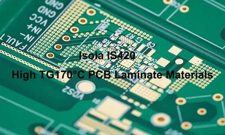
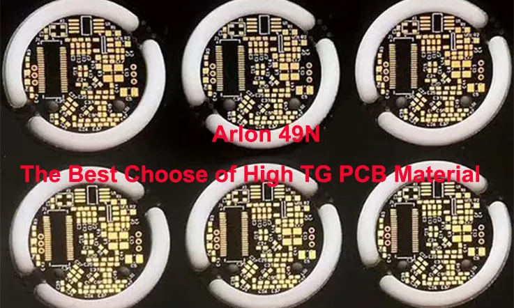
●Layer Stack-up and Material Selection: The choice of material is a main factor in high-frequency PCB design. Commonly used materials, like FR4, might work well for low-frequency boards, but high-frequency designs need specialized substrates, such as Rogers or Teflon-based materials, to ensure minimal signal loss and distortion. These materials help keep the signal integrity intact.
●Manufacturing Techniques: It’s not enough to just design the PCB; it needs to be manufacturable at scale. High-frequency designs require precision at every stage, from the via design to the trace width and stack-up configuration. This level of complexity means close communication with PCB manufacturer(JarnisTech) is essential, ensuring we can accommodate the design specifications and produce high-quality boards that maintain the desired performance.
This is why high-frequency PCB design requires specialized training and tools. You can’t simply use the same methods that work for low-frequency designs and expect great results. The stakes are higher, and so is the level of detail required.
Key Considerations in High-Frequency PCB Design
Designing high-frequency PCBs requires more than just knowing the basics of PCB design. There are numerous challenges that our engineers face, especially when working with high-speed signals. In high-frequency PCB design, issues like signal degradation, crosstalk, and jitter must be addressed to ensure the performance remains consistent. These challenges aren’t limited to just theoretical concerns—they directly impact circuit behavior and can affect the overall system functionality.
Understanding how these problems manifest and how to mitigate them is a first step in creating reliable high-frequency PCBs that function under high-speed conditions. Below, we’ll break down some of the primary challenges and strategies used to address them.
Understanding Signal Integrity in High-Frequency PCB Design
Signal integrity refers to the quality of signals as they travel through the PCB traces. In high-frequency circuits, preserving signal integrity becomes an even more delicate task due to the increased susceptibility to noise, interference, and signal degradation. We face the challenge of ensuring that the signal remains clear and accurate over its entire path, even at high speeds.
Main factors to preserve signal integrity in high-frequency PCB design include the following:
●Trace Layout: Careful planning of trace width, length, and positioning helps avoid signal degradation. Incorrect trace widths or placement can lead to impedance mismatches, causing reflections and signal loss.
●Via Design: In high-frequency PCB designs, vias can introduce unwanted inductance and resistance that affect signal transmission. To reduce these disruptions, it’s best to keep via lengths short and choose appropriate via types for the design. Proper via management helps maintain signal clarity and prevents performance issues in high-speed circuits.
●Impedance Matching: To prevent signal reflection, it’s necessary to ensure that the trace impedance aligns with both the source and load impedance. This can be done by adjusting the trace width and managing the PCB layout to maintain consistent impedance across the design.
Table: Impedance Matching Examples in High-Frequency PCB Design
| Trace Type | Recommended Impedance (Ω) | Trace Width (mil) | Dielectric Constant (εr) |
| Single-Ended | 50 | 5 | 4.5 |
| Differential Pair | 100 | 6 | 4.5 |
| Microstrip | 75 | 7 | 3.8 |
This table provides an example of trace widths and impedances for different types of high-frequency signal transmission, helping to ensure the signal integrity in high-speed PCBs.
Dealing with Signal Reflections and Losses in High-Frequency Designs
Signal reflections occur when there is a mismatch between the signal trace impedance and the impedance of the connected devices. This can cause signals to reflect back, leading to data corruption or signal loss. Managing these reflections is one of the most pressing challenges in high-frequency PCB design.
There are several strategies to mitigate signal loss and reflections:
●Minimize Impedance Mismatches: Matching the trace impedance to the device impedance is a fundamental practice in high-speed PCB design. Using simulation tools can help visualize and avoid these mismatches.
●Termination Resistors: In many high-speed designs, termination resistors are added to prevent reflections. These resistors match the impedance of the PCB trace, providing a smooth signal path and ensuring data is transmitted without degradation.
●Optimized Via Design: By minimizing the inductance and resistance of vias, we can reduce the signal loss associated with these components. For instance, micro-vias are often used in high-frequency designs because they offer less impedance disruption compared to traditional vias.
Table: Signal Reflection Comparison with and without Termination
| Configuration | Reflection Coefficient | Signal Loss (%) |
| No Termination | 0.85 | 50% |
| With Termination Resistor | 0.05 | 5% |
This table shows the significant difference in signal quality between circuits with and without termination resistors, highlighting the impact of termination in controlling reflections and losses.
Mitigating Crosstalk and Interference in High-Speed PCB Layouts
Crosstalk occurs when a signal from one trace interferes with another due to electromagnetic coupling. In high-frequency designs, crosstalk can significantly affect the performance and reliability of the circuit. Preventing this interference is a part of any high-speed PCB layout.
Several strategies are used to mitigate crosstalk and ensure a clean signal:
●Increasing Trace Separation: By increasing the spacing between signal traces, the likelihood of electromagnetic coupling is reduced. This technique works by minimizing the field overlap between traces carrying high-speed signals.
●Using Ground Planes: A well-designed ground plane can provide shielding between traces, helping to prevent crosstalk. Ground planes act as a barrier to external electromagnetic interference (EMI) and help maintain the signal integrity of the traces.
●Differential Pair Routing: For differential signals, maintaining a consistent and balanced routing is important. Keeping the traces as close to each other as possible can reduce the likelihood of crosstalk between differential pairs.
●Shielding: In certain designs, shielding is applied to protect sensitive traces from external interference. Metal shields or internal layers within the PCB can block unwanted signals, helping to maintain the integrity of the signal throughout the board.
Table: Effectiveness of Shielding in Reducing Crosstalk
| Shielding Type | Crosstalk Reduction (%) | Signal Integrity Impact |
| No Shielding | 50% | High interference |
| Conductive Shield | 90% | Improved signal quality |
| Grounded Shield | 98% | Near-perfect isolation |
This table shows how different types of shielding reduce crosstalk and improve signal integrity, demonstrating the importance of shielding in high-frequency PCB design.
Advanced PCB Layout Techniques for High-Frequency Signals
In high-frequency PCB design, the layout is a major factor influencing how well the final product performs. By adopting advanced PCB layout techniques, you can reduce signal loss, prevent signal degradation, and keep your circuits in top shape even at high speeds. In this section, we’ll explore some effective layout strategies to ensure your high-frequency designs meet performance standards.
By focusing on areas like minimizing vias, optimizing trace routing, and selecting the best PCB stack-up configurations, you can prevent issues like crosstalk, signal reflections, and losses that could disrupt your design’s operation.
Let’s dive into the strategies you can use to get your high-speed circuits on track.
Impedance Matching and Differential Pair Routing for High-Frequency Signals
When it comes to high-speed signal transmission, impedance matching is often one of the first things you think about. It plays a central role in helping signals travel smoothly through the PCB, without interference or loss of data. By adjusting trace widths and the board’s layout, the signal flow can be optimized for better performance.
Differential pairs work by running two traces close together, each carrying an opposite signal. This configuration helps cancel out unwanted noise and keeps the signal sharp, even as it travels across longer distances. Here’s what you need to know about making it work:
●Trace Width and Spacing: The width of the traces and the distance between them affect the impedance. If the impedance is mismatched, the signal will reflect, distorting the data.
●Maintaining Consistency: To keep the traces as parallel as possible and maintain consistent spacing. Any variation can upset the balance of the signal.
●Simulation Tools: Before finalizing your design, run simulation software to verify that the impedance is consistent throughout the PCB. This will help avoid mistakes that can be costly down the line.
Table: Typical Impedance Values for Differential Pairs
| Trace Type | Desired Impedance (Ω) | Trace Width (mil) | Trace Spacing (mil) |
| High-speed Signals | 100 | 6.0 | 6.0 |
| Low-speed Signals | 50 | 10.0 | 8.0 |
| RF Signals | 75 | 8.0 | 6.5 |
This table offers a quick reference for setting up differential pairs with impedance matching. Adjusting trace width and spacing ensures a steady flow of data through your circuit.
Best Practices for Via Placement and Trace Routing in High-Frequency PCBs
In high-frequency PCB design, the placement of vias and trace routing are major contributors to the overall performance of the PCB. Poorly placed vias can add unwanted resistance and inductance to the signal, slowing it down or causing it to degrade. Thoughtful planning of these aspects is necessary to keep the design functioning effectively.
Here are some strategies to optimize via placement and trace routing:
●Minimize Via Lengths: The longer a via is, the more inductance it introduces. Keeping vias as short as possible reduces their impact on the signal’s speed and quality.
●Consider Blind or Buried Vias: Blind or buried vias can help connect inner layers without affecting surface layers, keeping your signal routes clean and clear.
●Avoid Via Stubs: A via stub is a segment of the via that doesn’t connect to any layer. It can cause signal reflections. To avoid these, consider via-in-pad designs or adjusting routing paths.
●Microvias: For high-density interconnects (HDI) and more compact designs, microvias are the go-to option. They reduce signal loss and minimize the space needed for via connections.
Table: Comparison of Via Types for High-Frequency PCB Design
| Via Type | Characteristics | Ideal Use Case | Impact on Signal Integrity |
| Through Hole Vias | Traditional, simple, but long | Low-speed or less dense designs | Higher resistance, not great for high-speed signals |
| Blind Vias | Connects outer layers to inner layers | Complex designs, multi-layer PCBs | Better for high-frequency signals than through hole |
| Microvias | Small, low inductance, short | High-density interconnects (HDI) | Preferred for high-frequency designs |
| Stacked Vias | Multiple vias stacked vertically | High-density designs | Reliable connections, helps reduce impedance issues |
Layer Stack-Up Design for High-Frequency PCB Layouts
The design of your PCB stack-up is another factor in ensuring signal integrity. The layer stack-up controls how the traces, power, and ground planes are arranged, and it can have a big impact on how well the PCB handles high-frequency signals.
Here are some best practices for designing a stack-up that supports high-frequency signals:
●Use Solid Ground Planes: A solid ground plane underneath the signal layers helps maintain a stable reference, while also shielding against unwanted EMI.
●Signal Layer Placement: Position high-speed signal layers between ground planes to maintain a consistent impedance and reduce the likelihood of signal interference.
●Power Planes: Power planes provide consistent voltage and help reduce noise, while also contributing to better signal integrity when placed close to ground planes.
●Symmetry: A symmetric stack-up helps avoid warping and ensures even signal distribution across the PCB, which is particularly beneficial in multi-layer high-frequency designs.
Table: Example of Layer Stack-Up for High-Frequency PCB Design
| Layer Number | Type | Thickness (mil) | Function |
| 1 | Signal Layer | 0.5 | High-speed signal routing |
| 2 | Ground Plane | 1.0 | Signal shielding, EMI reduction |
| 3 | Signal Layer | 0.5 | High-speed signal routing |
| 4 | Power Plane | 1.0 | Consistent power distribution |
| 5 | Ground Plane | 1.0 | Signal shielding, EMI reduction |
| 6 | Signal Layer | 0.5 | High-speed signal routing |
High-Frequency PCB Design Tools and Software
Designing high-frequency PCBs isn’t just about creativity—it’s about precision and working with advanced technology. High-frequency PCB design tools and simulation software are indispensable for ensuring your designs meet the necessary performance standards. With the increasing demand for 5G networks, RF modules, and automotive radar systems, we must rely on the right set of tools to simulate, validate, and optimize their layouts before moving into production.
In this section, we will take you through some of the most widely used tools and software for high-frequency PCB design. These options can assist in everything from signal integrity analysis to thermal performance optimization, ensuring your high-frequency designs function optimally across a variety of applications.
Top Simulation Software for High-Frequency PCB Design
Simulation software plays an integral role in high-frequency PCB design by allowing designers to evaluate how their designs will perform in real-world conditions before production starts. This software helps visualize signal behavior and provides insights into potential issues that could arise in the design phase, allowing adjustments to be made to enhance the overall performance of the board. Choosing the right simulation platform can significantly affect how well the design will function once manufactured. Below are some of the simulation software options commonly used in high-frequency PCB design:
●Ansys HFSS: Known for its electromagnetic simulation capabilities, Ansys HFSS is an industry standard for simulating how RF signals travel through a PCB. Using Ansys, you can model aspects such as impedance matching, signal integrity, and electromagnetic interference (EMI). It’s particularly useful for RF circuit design, allowing designers to visualize and mitigate signal issues early in the design process.
●Keysight ADS (Advanced Design System): Keysight ADS is widely used for simulating high-speed signals. Its features are tailored to signal integrity analysis, offering a comprehensive environment for testing signal quality, thermal performance, and power integrity. Keysight is especially favored for RF circuits and works well for automotive radar systems and wireless communication devices.
●Cadence Sigrity: Cadence Sigrity provides robust simulation tools focused on signal integrity. It’s perfect for analyzing via effects, crosstalk, and transmission line effects, making it a great fit for designers working with multi-layer PCBs and high-speed routing. Its simulation capabilities are excellent for understanding how your design will handle the electromagnetic challenges that come with high-frequency circuits.
PCB Design Tools for Efficient Routing and Layout
Once you’ve simulated your high-frequency circuit, the next step is laying out the PCB. Here’s where having the right PCB design tools can make all the difference. These tools help to optimize your trace routing and via design, ensuring the signals flow smoothly and without unnecessary interference. Whether you’re dealing with differential pair routing or fine-tuning impedance matching, using specialized PCB design software can help speed up the process and prevent common design flaws.
●Altium Designer: Altium Designer is recognized for its automatic routing features, making it good for complex high-speed designs. It offers tools for differential pair routing, which is crucial in high-frequency PCB designs where preserving signal integrity is a must. Altium also allows for automatic creation of layer stack-ups, which simplifies the process of managing multi-layer PCBs.
●Autodesk Eagle: While Eagle is often used for simpler designs, it’s still capable of handling high-frequency circuits. It’s particularly useful for small RF modules or low-cost designs that need an easy-to-use interface. Eagle provides essential tools for signal routing, ensuring that even high-frequency PCBs can be laid out properly without extensive manual adjustments.
●Mentor Graphics Xpedition: Xpedition is a tool designed for high-performance PCB designs, offering features that support advanced signal integrity analysis and routing optimization. It accommodates high-density interconnects (HDI), which are useful for multi-layer designs where managing trace length and impedance alignment is necessary. This platform is a solid option for engineers working on complex, multi-layer high-frequency PCBs, providing tools that help ensure the design meets the desired specifications.
Utilizing 3D PCB Design Tools for High-Frequency Simulations
Once you’ve optimized the routing and layout, the next step is to visualize how your high-frequency design will function in a 3D space. 3D PCB design tools allow you to assess your design’s overall structure and performance, ensuring that it meets all of the necessary specifications. These tools are particularly useful for seeing how high-frequency signals behave in a complex, multi-layer PCB and making any final adjustments before physical prototypes are built.
●SolidWorks PCB: SolidWorks PCB integrates with 3D CAD designs, giving you a clear picture of how your PCB fits within the larger product design. You can visualize trace routes, check for any potential collisions or mechanical conflicts, and optimize the design for thermal management. This is especially useful in high-tech devices where the PCB must fit perfectly within the device without interference.
●Siemens NX: Siemens NX offers 3D PCB design and electromagnetic analysis, which helps simulate signal behavior in complex environments. This is particularly helpful for designs that require detailed analysis of how the signals travel through multiple layers and how they might be affected by external factors such as thermal expansion or electromagnetic interference.
●Autodesk Fusion 360: Fusion 360 brings together electrical and mechanical design, making it an excellent choice for designs that need a multi-disciplinary approach. Using Fusion 360, we can check for potential interferences and validate how high-frequency signals interact with the rest of the product design. This is especially useful for IoT devices, wearables, and smart automotive systems.
How to Optimize High-Frequency PCB Prototyping and Testing?
When developing high-frequency PCBs, the transition from digital simulation to physical prototype testing is where many of the design assumptions are validated. The ability to physically measure and adjust for factors like signal integrity, signal loss, and thermal characteristics is a major part of ensuring a design performs correctly in real-world applications. Testing is an ongoing process that allows designers to improve the overall layout and address any potential failures in the design before going into production.
In this section, we will take a deep dive into the steps for effective prototyping and testing high-frequency PCBs. From using proper test benches to incorporating specific test tools, we’ll guide you through best practices for improving your high-frequency design accuracy.
Best Practices for Prototyping High-Frequency PCBs
Prototyping high-frequency designs requires precision and careful setup. The process begins with creating a well-equipped test bench, which includes instruments like oscilloscopes, signal probes, and network analyzers. Each tool has a specific function in assessing different aspects of signal transmission, helping to verify that the PCB performs according to the design requirements.
●Oscilloscopes are invaluable when observing the waveform of high-frequency signals, as they provide real-time visibility into how signals travel through the PCB.
●Signal probes allow you to inject test signals into specific points on the PCB to analyze the resulting responses.
●Network analyzers allow you to measure the frequency response of the design, which is particularly helpful for testing RF components.
Using these tools together provides a real-time analysis of the signal integrity, enabling you to identify problems such as signal degradation and impedance mismatches early on.
Testing High-Frequency Signals and Components in the Prototype Stage
Testing in the prototype stage involves using sophisticated tools to evaluate the actual behavior of your high-frequency signals and components. It’s at this stage that you check for signal reflection, attenuation, and loss—issues that often aren’t visible in the simulation stage.
●Time Domain Reflectometers (TDRs) are typically used to detect impedance mismatches and signal reflections along traces and vias, ensuring that the signal travels without disruption.
●Network analyzers allow for in-depth analysis of frequency response, checking for any discrepancies in the expected performance of the RF components.
●Signal analyzers help verify signal quality during both transmission and reception, helping pinpoint areas that might cause errors or failures in communication.
| Tool | Purpose | Application |
| TDR (Time Domain Reflectometer) | Measures impedance discontinuities | Helps detect problems in trace routing and signal loss |
| Network Analyzer | Evaluates frequency performance | Verifies RF components and signal transmission quality |
| Signal Analyzer | Analyzes signal quality during transmission | Ensures signal integrity for accurate data transmission |
Using these tools allows for detailed troubleshooting, helping you pinpoint specific issues such as signal loss or distortion that might arise during signal transmission.
Design Iterations and Improvements Based on Prototype Testing
Once you’ve completed the initial testing and gathered feedback, the next step is to iterate. Prototyping is not about getting the design perfect on the first try—it’s about refining the design through careful testing and improvements. Each round of testing and evaluation brings new insights, helping you adjust the design to optimize performance.
For example, if you notice signal loss during testing, you might decide to adjust the trace width or via design to minimize the loss. If there are signal reflections, you can modify the stack-up or differential pair routing to fix the impedance mismatch. This iterative process is necessary for improving the overall performance of the high-frequency PCB.
Below is a table showing common testing results and potential design changes based on feedback:
| Issue Detected in Testing | Suggested Adjustments | Outcome of Adjustments |
| Signal Reflection | Modify trace width and via design | Improves signal quality and reduces reflections |
| Impedance Mismatch | Adjust routing and stack-up configuration | Results in better signal integrity |
| High Signal Attenuation | Revise via placement and differential pair routing | Enhances signal transmission performance |
| Excessive EMI | Incorporate shielding and ground planes | Reduces electromagnetic interference |
By using the data gathered from these tests, you can implement design improvements that directly enhance the PCB’s ability to handle high-frequency signals.
Material Selection for High-Frequency PCB Design
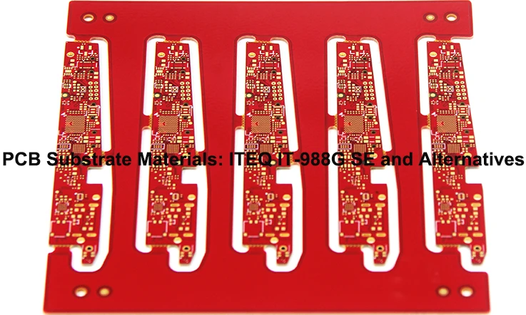
Selecting the right materials for high-frequency PCBs is a core part of the design process, especially when considering how these materials influence signal integrity, performance, and cost. As high-frequency signals experience greater resistance and signal loss, the materials chosen must be suited to handle these characteristics. Material selection impacts the behavior of the PCB at high frequencies, particularly in high-speed data transmission, signal reflection, and impedance control. With multiple options available, our design engineer needs to understand the differences between materials like Rogers, PTFE, and FR4 to make an informed choice based on performance requirements and cost constraints.
Comparing High-Frequency PCB Materials: Rogers, FR4, and PTFE
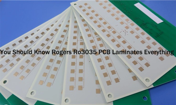
Different materials provide different benefits, and understanding how they impact your design is essential. In high-frequency applications, some materials outperform others based on their dielectric properties, loss tangents, and thermal performance. Rogers and PTFE (Teflon) are popular materials for high-frequency applications, offering low signal loss and stable performance in high-speed circuits. However, they come at a higher cost compared to standard FR4.
Here’s a quick comparison of these materials:
| Material | Dielectric Constant (Dk) | Loss Tangent (Df) | Thermal Stability | Cost |
| Rogers | 2.2 – 10.2 | 0.002 – 0.003 | High | $$$$ |
| FR4 | 4.5 – 5.5 | 0.02 – 0.03 | Moderate | $$ |
| PTFE (Teflon) | 2.1 – 2.5 | 0.0002 – 0.0004 | Very High | $$$$ |
●Rogers: Known for its low loss tangent and excellent thermal stability, making it suitable for high-speed, high-frequency applications.
●FR4: The most common material for low-cost PCBs, but its higher loss tangent limits its performance at high frequencies.
●PTFE (Teflon): Preferred for ultra-high-frequency circuits due to its low loss tangent and superior dielectric properties but comes at a higher price point.
Choosing the Right Material-
●For high-speed digital applications, Rogers is the best due to its low signal loss and superior handling of high frequencies.
●FR4 is sufficient for lower-frequency designs where cost is a significant factor.
●PTFE should be considered for extremely high-frequency applications like RF or microwave circuits where performance cannot be compromised.
How Dielectric Constant Affects High-Frequency PCB Design?
The dielectric constant (Dk) of a material influences how quickly signals travel through a PCB. A lower Dk value generally leads to faster signal transmission, while a higher Dk can cause delays and increase the potential for signal distortion. For high-frequency PCBs, choosing materials with the right Dk helps ensure that signals remain strong and coherent over longer distances and through complex routing paths.
| Material | Dielectric Constant (Dk) | Signal Propagation Speed |
| Rogers | 2.2 – 10.2 | High |
| FR4 | 4.5 – 5.5 | Moderate |
| PTFE (Teflon) | 2.1 – 2.5 | Very High |
Impact on High-Frequency Designs-
●Lower Dk (e.g., Rogers and PTFE): Better for high-speed data transmission as the signal travels faster through the material with minimal loss.
●Higher Dk (e.g., FR4): Used in applications where performance demands are not as strict, but at a reduced cost.
Tips for Managing Dielectric Constant in Design-
●For high-speed applications, choose materials with a lower Dk to reduce propagation delay and signal attenuation.
●Consider how Dk interacts with the board’s geometry to optimize routing for minimal signal degradation.
Material Considerations for High-Speed Data Transmission
When it comes to high-speed data transmission, materials must be selected based on their performance at gigahertz frequencies. The key considerations include low signal loss, minimal crosstalk, and stable impedance. Materials like Rogers and PTFE are commonly used in high-speed designs, but the choice of material should also align with the required mechanical properties, such as thermal stability and flexibility for specific applications.
| Material | Loss Tangent (Df) | Impedance Control | Suitability for High-Speed Data |
| Rogers | 0.002 – 0.003 | Excellent | High |
| FR4 | 0.02 – 0.03 | Moderate | Moderate |
| PTFE (Teflon) | 0.0002 – 0.0004 | Excellent | Very High |
Material Considerations for High-Speed Data-
●Rogers and PTFE are preferred materials for high-speed data transmission due to their low loss tangent and effective impedance control. These properties help minimize signal degradation, ensuring high-quality signal integrity in demanding high-frequency applications.
●FR4 is less suitable for high-speed data transmission due to its higher loss tangent and reduced ability to maintain stable impedance, though it remains a cost-effective choice for less demanding applications.
Best Practices for High-Speed Data Transmission Materials-
●Select materials with low loss tangent and high dielectric stability for high-frequency designs to minimize signal degradation.
●Ensure accurate impedance control to prevent signal reflections, which could interfere with data transmission and disrupt the performance of the PCB.
Cost Considerations in High-Frequency PCB Design and Manufacturing
When designing and manufacturing high-frequency PCBs, managing costs is an integral part of the decision-making process. These costs can quickly accumulate due to the specialized materials, precise manufacturing processes, and necessary quality checks in both design and production. The challenge is to balance performance, reliability, and cost-efficiency.
High-frequency PCB designs often require particular materials, specific manufacturing techniques, and thorough testing to ensure performance, signal integrity, and durability. Understanding the breakdown of these costs and identifying areas where optimization can occur helps to make informed decisions that satisfy both performance needs and budget constraints.
Understanding the Costs of High-Frequency PCB Materials and Manufacturing
High-frequency PCBs use specialized materials that differ significantly from those used in standard PCBs. Materials such as high-dielectric substrates (e.g., Rogers, Teflon) and low-loss laminates come at a higher cost. The manufacturing process also contributes to the overall expense, including steps like controlled impedance routing, multilayer stacking, and via filling.
Here’s a breakdown of typical material costs in high-frequency PCB design:
| Material Type | Cost Range (USD/sq ft) | Performance Characteristics |
| Rogers 4003C | $30 – $50 | Low loss and stable performance at high frequencies |
| Teflon (PTFE) | $40 – $80 | Excellent dielectric properties suitable for high-frequency signals |
| FR4 (Standard) | $5 – $15 | Limited use in high-frequency applications |
| HDI Materials | $25 – $45 | Used for compact layouts and multilayer designs |
The production of high-frequency PCBs often requires advanced techniques, such as laser drilling or micro-via formation, which demand specialized equipment and increase manufacturing costs.
Cost Optimization for Materials-
●Choose for hybrid materials that combine cost-effective and high-performance characteristics.
●Negotiate with suppliers for better rates on high-frequency materials when ordering in larger quantities.
●Consider using thinner laminates for certain designs to reduce material expenditure.
Design Choices that Impact the Cost of High-Frequency PCBs
Design decisions have a direct effect on the total cost of a high-frequency PCB. Several factors, such as the number of layers, trace width, and via density, can significantly influence the cost structure. For instance, increasing the number of layers enhances design complexity, leading to higher material and production costs.
The following table illustrates how different design choices can impact overall costs:
| Design Factor | Impact on Cost | Considerations for Cost-Effective Design |
| Number of Layers | More layers increase material and processing costs | Limit the layers to what is necessary for design integrity |
| Trace Width | Narrow traces require high-precision etching | Balance trace width with manufacturing capabilities |
| Via Density | High via density increases manufacturing complexity | Minimize via usage without compromising signal quality |
| Differential Pair Routing | Adds complexity for controlled impedance, leading to more cost | Simplify routing to keep costs lower when possible |
By carefully considering these design factors, it’s possible to minimize unnecessary complexity, thereby lowering production costs without affecting the overall performance of the PCB.
Optimization Recommendations-
●Reduce the number of layers where possible, especially for designs that do not demand extensive functionality.
●Simplify trace routing to avoid overuse of vias and minimize the overall complexity.
●Design with manufacturability in mind, ensuring your design aligns with available capabilities to avoid costly adjustments.
Cost-Saving Tips for High-Frequency PCB Design
Although high-frequency PCBs generally involve higher costs, there are ways to reduce these expenses without affecting the design quality. Cost-saving strategies focus on making design and manufacturing choices that help streamline production, without compromising signal quality or performance.
| Cost-Saving Technique | Description | Estimated Savings |
| Reduce PCB Size | Smaller PCBs reduce material costs and simplify handling | 10% – 20% savings |
| Standard Components | Using off-the-shelf components reduces custom design costs | 15% – 25% savings |
| Outsource Manufacturing | Manufacturing in regions with lower labor costs can cut expenses | 20% – 30% savings |
| Design for Manufacturability (DFM) | Optimize designs to minimize the need for revisions or rework | 5% – 15% savings |
Testing is another area where cost savings can be realized. Automated testing methods such as ATE (Automatic Test Equipment) or in-circuit testing (ICT) can lower labor costs associated with manual inspections. Additionally, conducting iterative testing can help identify issues early on, thus avoiding expensive revisions later in the prototyping stage.
Additional Cost-Saving Measures-
●Invest in early-stage prototyping to identify design flaws early in the process, reducing the chances of expensive rework.
●Work closely with your PCB manufacturer to identify more cost-effective production methods.
●Use design tools that allow for greater accuracy and less need for physical prototypes, thus reducing testing and revision costs.
Regulatory Compliance in High-Frequency PCB Design and Manufacturing
High-frequency PCBs must align with specific industry standards and regulatory frameworks to ensure they meet performance, safety, and environmental benchmarks. Compliance with standards like IPC-2221, RoHS, and UL certifications is crucial in validating the PCB’s reliability, functionality, and environmental compatibility. This section will cover standards that influence high-frequency PCB design and manufacturing, helping professionals stay on track with regulations.
Understanding IPC Standards for High-Frequency PCB Design
The IPC-2221 standard defines the requirements for PCB designs, including those for high-frequency circuits, to ensure precise signal integrity and layout. Adhering to IPC-2221 involves factors like trace width, via design, and impedance control—main elements in optimizing high-frequency performance.
To maintain optimal signal integrity and reduce interference, we should consider IPC-2221 guidelines regarding trace spacing and routing. The table below highlights IPC-2221 recommendations for high-frequency PCB design.
| Design Aspect | IPC-2221 Standard Recommendation | Impact on High-Frequency Design |
| Trace Width | Defined based on impedance and frequency requirements | Ensures consistent impedance control |
| Via Design | Minimize via length, use controlled impedance vias | Reduces signal degradation |
| Impedance Control | Defined for signal paths, matched for differential pairs | Prevents signal reflections |
| Crosstalk Prevention | Separation of traces and controlled routing layers | Minimizes interference |
These guidelines help maintain signal quality and ensure that designs are optimized for high-frequency operations.
Navigating RoHS Compliance in High-Frequency PCB Manufacturing
RoHS (Restriction of Hazardous Substances) compliance is a mandatory regulation that limits the use of certain hazardous materials in electronic components, including PCBs. For high-frequency PCBs, RoHS compliance involves carefully selecting materials that meet environmental requirements without compromising performance.
Materials such as lead-free solder and specific halogen-free laminates are commonly used in high-frequency boards to comply with RoHS standards. The table below outlines the typical RoHS-compliant materials used in high-frequency PCB production.
| Material Type | RoHS Compliance Requirement | Alternative Materials |
| Solder | Lead-free, typically Sn-Ag-Cu alloys | Sn-Ag-Cu solder paste |
| PCB Laminates | Halogen-free, flame-retardant options | FR4, Rogers RO3000 series |
| Resistors and Capacitors | No use of cadmium, mercury, lead | Lead-free components |
Navigating these RoHS materials ensures that high-frequency PCBs remain compliant while maintaining their functional integrity.
UL Certification for High-Frequency PCB Reliability
UL (Underwriters Laboratories) certification ensures that a product meets safety standards in various conditions. For high-frequency PCBs, UL certification confirms the design’s safety, including electrical performance and environmental durability, especially in sectors like automotive, aerospace, and medical applications.
The certification process involves testing the PCB for flammability, electrical conductivity, and mechanical stress resistance. Below is a table summarizing the common types of tests performed during UL certification for high-frequency PCBs.
| Test Type | UL Standard | Purpose of Test |
| Flammability Testing | UL 94 | Ensures materials do not catch fire easily |
| Electrical Stress Test | UL 746A | Verifies safe electrical performance under load |
| Environmental Stress Test | UL 746C | Tests PCB performance under varying temperature |
| Dielectric Strength Test | UL 506 | Ensures insulation can withstand high voltages |
FAQs related to High-Frequency PCB Design
1. How do high-frequency signals interact with PCB parasitics?
Parasitic inductance and capacitance of traces, vias, and components can cause signal distortion. These effects can be reduced by carefully controlling layout and trace geometry.
2. What types of signal losses should be considered in high-frequency PCB design?
Signal losses in high-frequency PCBs include skin effect losses, dielectric losses, and conductor losses. These must be minimized by selecting appropriate materials and design techniques.
3. What is the importance of via-in-pad design in high-frequency PCB layout?
Via-in-pad is a design practice where a via is placed directly under a component pad. This can be used for high-frequency designs but must be managed carefully to avoid signal degradation.
4. How do microstrip and stripline differ in high-frequency PCB design?
Microstrip lines are placed on the outer layer of the PCB, while striplines are sandwiched between two dielectric layers. Each has different performance characteristics in terms of impedance control and signal loss.
5. Can high-frequency PCBs be used in flexible designs?
Yes, high-frequency PCBs can be designed with flexible substrates, though materials must be chosen carefully to maintain signal integrity in dynamic applications.