The technology landscape is in a state of constant change, and this is especially true for Battery PCB design. As industries continue to push the boundaries of what’s possible, the demand for Battery PCBs that deliver high efficiency, exceptional durability, and advanced features is becoming more pronounced.
This article will take a closer look at how Battery PCBs are adapting to the shifting needs of the automotive, consumer electronics, and energy storage sectors, as well as the challenges facing PCB design engineers and manufacturers in creating these components.
Understanding the Role of Battery PCB in Modern Energy Solutions
The landscape of technology is continuously evolving, and Battery PCBs are at the heart of this transformation. Whether it’s electric vehicles, consumer electronics, or energy storage systems, the need for Battery PCBs that efficiently manage power distribution and ensure battery safety is only growing. This section offers an introduction to what Battery PCBs are, how they work within Battery Management Systems (BMS), and why they’re becoming an indispensable part of modern energy solutions across different industries.
What is Battery PCB and Its Function?
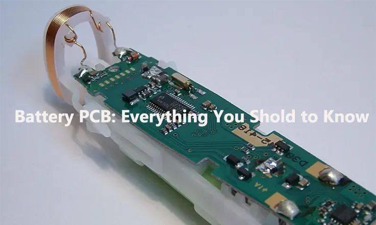
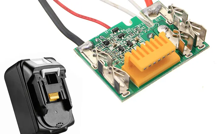
A Battery PCB—also known as a Battery Printed Circuit Board—is the specialized circuit board found in battery systems. These PCBs are designed to regulate and manage the flow of electrical power within battery packs to ensure consistent performance and prevent potential issues like overheating or short-circuiting. Unlike standard PCBs that handle everyday electrical components, Battery PCBs are built to withstand the electrical and thermal stress that comes with storing and distributing energy.
In modern battery-operated devices, these PCBs handle a variety of tasks: from voltage regulation to charge balancing. For instance, in an electric vehicle (EV) battery, the Battery PCB helps maintain equal charge levels across all the cells, preventing any single cell from overcharging or discharging too much. As a result, Battery PCBs help extend the battery’s life while maximizing its energy output.
Example: Take your smartphone, for example. Inside its battery, the Battery PCB manages the flow of energy, ensuring that your device gets enough power without risking the health of the battery. If this system didn’t exist, your battery could overcharge or even fail prematurely. Thanks to Battery PCBs, your phone’s power is managed and maintained throughout its life.
How Does a Battery PCB Fit Into a Battery Management System (BMS)?
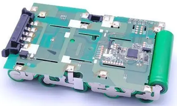
The Battery PCB is an integral part of a Battery Management System (BMS), working alongside sensors and controllers to monitor and control the battery pack’s performance. The BMS relies on the Battery PCB to perform tasks like cell balancing, overcharge protection, and temperature control. By ensuring that each individual cell within the battery pack is charged evenly and stays within safe operating parameters, the Battery PCB contributes to the overall health and longevity of the battery.
For example, when a vehicle’s battery pack is being charged, the Battery PCB within the BMS continually monitors the voltage and current levels across all the cells. It adjusts the charging rates and ensures no cell receives too much or too little energy. This precise balancing process helps prevent battery failures or malfunctions that could occur in the absence of such management.
Fun fact: Ever wonder why electric vehicles can go for hundreds of miles on a single charge? That’s in part thanks to the Battery PCBs in their BMS, which optimize power distribution across the battery cells.
Applications of Battery PCB Across Different Industries
From electric vehicles to portable electronics, Battery PCBs are finding their way into a wide variety of industries. Let’s take a look at a few of the key sectors that depend on Battery PCBs to power their products.
Automotive Industry (Electric Vehicles and Hybrid Cars)-
Battery PCBs are used in electric vehicle (EV) and hybrid car batteries to handle the heavy-duty task of distributing power efficiently. The Battery PCB ensures the battery operates smoothly by balancing energy across cells and preventing overheating during high energy usage, especially when accelerating or braking.
Consumer Electronics (Smartphones, Laptops, Wearables)-
Battery PCBs are the brains behind your device’s battery, ensuring energy efficiency and safety. These PCBs handle tasks such as charge management, temperature regulation, and power distribution. Whether it’s your smartphone, laptop, or smartwatch, Battery PCBs ensure that your device gets the most out of its battery.
Renewable Energy Storage Systems-
In renewable energy, particularly solar, Battery PCBs manage the storage and distribution of energy collected from solar panels. These PCBs ensure that the energy is stored safely and that it can be released as needed to power homes, businesses, or even off-grid applications.
Differences Between a Battery PCB and a BMS
When comparing Battery PCBs and Battery Management Systems (BMS), there are several differences in terms of hardware design, functionality, and usage.
1.Hardware Components
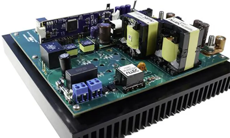
At a fundamental level, Battery PCBs typically consist of MOSFETs, integrated circuits, capacitors, and resistors. These components work together to protect the battery pack from common issues such as overcharging, overcurrent, and short circuits. The Battery PCB is largely focused on safety and basic protection.
In contrast, a BMS integrates more advanced components, notably a microcontroller paired with sophisticated software. This combination allows the BMS to perform not just basic protection, but also complex tasks like calculating the state of charge (SOC), monitoring battery health, and making real-time decisions on system operation.
2.Precision and Monitoring
The precision of these two devices also varies significantly. A Battery PCB focuses on safeguarding the battery and does not have the capability to monitor the SOC or battery health. It lacks the intelligence to interpret measurements or perform detailed calculations.
The BMS, however, is equipped with algorithms that continuously track multiple parameters like SOC, state of health (SOH), and voltage levels across the cells. It provides data-driven insights, helping optimize the battery’s operation and extend its lifespan.
3.Steering Capabilities
While a Battery PCB cannot directly control how the battery or charging system behaves, a BMS is designed to communicate with other devices in the system. Using communication protocols such as MODBUS, I2C, and CAN, a BMS can relay instructions to external components, including chargers and electric motors. This enables the BMS to manage power distribution, adjust charging rates, and even control the motor’s behavior in electric vehicles or other applications.
4.Performance in Low-Temperature Conditions
In terms of low-temperature performance, Battery PCBs tend to be more stable than BMS units, which may struggle under extreme cold. BMS systems often experience issues such as signal instability or reduced functionality when operating in low temperatures. This can impact the accuracy of readings and control over the battery system.
5.Cost and Complexity
Lastly, when it comes to pricing, Battery PCBs are generally more affordable. Their design focuses mainly on protecting the battery, making them simpler and more cost-effective. On the other hand, BMS systems are more advanced, with their added functionalities—such as monitoring and communications—resulting in higher production costs.
PCB/PCM vs. BMS: Which One Is the Better Fit?
When deciding between PCB/PCM (Protection Circuit Board/Module) and BMS (Battery Management System), it’s not a simple “better or worse” scenario. Both of these components play a role in battery protection, but their functions differ, and each has its place depending on the application.
1.PCB/PCM (Protection Circuit Board/Module)
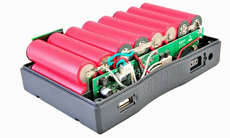
A PCB or PCM is a small but essential circuit board designed to provide protection for individual battery cells. These circuits monitor and prevent issues like overcharging, over-discharging, and short-circuiting. The simplicity of PCBs makes them an affordable and effective solution for single-cell applications where advanced functions are not necessary.
However, PCBs lack the ability to monitor or regulate the performance of the entire battery pack. They don’t have the smarts to balance the charge across cells or perform deeper analytics. As a result, PCBs are best suited for smaller applications, like single-cell batteries found in smartphones or portable electronics, where the primary need is basic protection against common battery failures.
2.Battery Management System (BMS)
In contrast, A BMS is a more advanced system that oversees the health and operation of an entire battery pack. Unlike a Battery PCB, which mainly provides protection, a BMS also monitors temperature, balances cells, and estimates the state-of-charge (SOC). This is particularly useful for larger, more complex battery setups like those in electric vehicles (EVs) or energy storage systems.
The BMS is built to handle multiple cells in a pack, ensuring that each one performs within its safe limits. It provides data on battery health, and some advanced systems are even equipped to communicate with external devices via protocols like CAN or MODBUS. With a BMS, you get advanced monitoring, cell balancing, and real-time data that ensures the battery pack’s performance stays in check over time.
3.Choosing the Right Solution for Your Application
If you’re dealing with a single-cell battery pack, like those found in mobile devices, a PCB/PCM is likely the right choice. It’s a cost-effective and simple solution that provides sufficient protection without adding complexity.
However, when working with larger battery packs—especially those that include 20 or more cells, such as in electric cars or large-scale energy storage systems—a BMS is a must. Not only does it provide protection, but it also delivers advanced management to keep the system performing at its best.
For smaller systems (under 20 cells), PCBs or PCMs offer protection and cost efficiency, making them ideal for consumer electronics or portable power solutions. For larger applications, though, the BMS is the way to go—it offers the precision, scalability, and data collection needed to manage multi-cell configurations.
Core Principles of Battery PCB Design
Designing Battery PCBs requires a blend of technical know-how and practical considerations. From thermal management to power efficiency, the design principles must accommodate the unique needs of systems that power various applications like electric vehicles (EVs) and consumer electronics. This section covers the core principles involved in Battery PCB design, ensuring that each design is optimized for long-lasting performance and reliability. The focus here is on maintaining efficiency in both high-energy systems and more compact, space-constrained devices.
Designing for Thermal Management in Battery PCB
Excessive heat is a major concern when designing Battery PCBs, as it can cause system failures. Effective thermal management ensures that energy systems operate without compromising on performance. Incorporating heat sinks, thermal vias, and insulating materials into the design can significantly reduce the likelihood of overheating.
Thermal vias are small copper-plated holes that enable heat dissipation by transferring heat from one side of the board to another. Heat sinks spread the heat across a larger surface area, helping it to cool down more rapidly. When designing Battery PCBs for electric vehicle batteries or power tools, our engineers often turn to these methods to prevent damage from heat buildup.
Common Thermal Management Techniques in Battery PCB Design-
| Technique | Description | Application |
| Thermal Vias | Copper-plated holes that help dissipate heat from critical components. | Used in EV batteries and power tools |
| Heat Sinks | Metal fins that absorb and spread heat away from the board. | Common in consumer electronics like laptops |
| Insulating Materials | Materials like ceramic or thermal pads that prevent heat from transferring to sensitive components. | Used in renewable energy storage |
Power Efficiency in Battery PCB Design
To make the most out of the energy stored within a battery, optimizing power flow within Battery PCBs is essential. Voltage regulation is a technique that ensures the battery’s charge remains at an ideal level, preventing overcharging and undercharging. Current flow optimization ensures that power is distributed as efficiently as possible across various components, which helps extend battery life.
Battery PCBs with voltage regulation circuits help maintain a steady power output, preventing overloads and ensuring devices operate smoothly. In systems like electric vehicles and solar-powered devices, regulating power flow is necessary to improve performance and extend battery life. These circuits carefully manage voltage levels, allowing the battery to work efficiently and keeping the system running without interruptions.
High-Density PCB Layouts for Compact Battery Designs
With the demand for smaller, more efficient devices increasing, the design of Battery PCBs is pushing the limits of space efficiency. In compact battery designs, optimizing every inch of the board is necessary. High-density PCB layouts allow us to fit essential components into smaller areas, while maintaining performance and safety standards.
Therefore, our PCB designers use techniques like multi-layer PCBs to maximize space and surface-mount technology (SMT) to reduce component size. These methods ensure that even the most space-constrained devices, like wearable devices, can achieve powerful energy management without compromising on functionality.
Techniques for High-Density PCB Layouts-
| Technique | Description | Application |
| Multi-Layer PCBs | Layers of circuitry stacked on top of each other to maximize space. | Wearable devices, smartphones |
| Surface-Mount Technology | Smaller components mounted directly on the surface of the PCB. | Consumer electronics, compact devices |
| Fine-Pitch Components | Use of smaller components to reduce PCB space requirements. | High-density systems, medical devices |
Protection and Safety in Battery PCB Design
As Battery PCBs are becoming a central component in modern systems such as electric vehicles, consumer electronics, and energy storage solutions, their safety features are increasingly emphasized. These measures are designed to safeguard users and the environment while also enhancing the performance and lifespan of the batteries. Battery-powered devices face risks like overcharging, overcurrent, short circuits, and voltage spikes, making the integration of reliable protection circuits necessary.
In this section, we explore the core safety features integrated into Battery PCBs. These protective mechanisms—such as overcharge protection, overcurrent protection, and short-circuit prevention—are designed to ensure that the battery operates within safe limits, while also enhancing its overall efficiency and lifespan. These measures allow Battery PCBs to function efficiently across different applications, from electric vehicles to renewable energy storage solutions.
Overcharge and Overcurrent Protection in Battery PCBs
Overcharging and overcurrent are two of the most common causes of battery failure. Overcharging occurs when a battery is charged beyond its safe voltage limit, leading to overheating and potential damage. To prevent this, Battery PCBs integrate overcharge protection circuits, which actively monitor the battery’s voltage and shut off the charging process once a safe threshold is reached.
Similarly, overcurrent occurs when the battery is subjected to a current higher than it is designed to handle. This can cause excessive heat generation and reduce the lifespan of both the battery and the connected devices. Battery PCBs incorporate current-limiting resistors, fuses, and transistors to control the current flow and prevent any overcurrent condition.
The following table highlights typical overcharge and overcurrent thresholds for different types of batteries and their corresponding protection circuit specifications:
| Battery Type | Overcharge Threshold | Overcurrent Threshold | Protection Circuit Type |
| Li-ion (Lithium-ion) | 4.2V per cell | 1.5C (1.5x rated capacity) | MOSFET-based overcharge cutoff |
| LiFePO4 (Lithium Iron Phosphate) | 3.65V per cell | 1.2C | Fuse & PPTC protection |
| NiMH (Nickel-Metal Hydride) | 1.45V per cell | 2C | Thermal cutoff + fuse |
These values represent the upper limits of charge and discharge that are considered safe for each battery type. By incorporating these protection circuits, Battery PCBs help mitigate risks associated with overcharge and overcurrent conditions.
Preventing Short-Circuits and Voltage Spikes in Battery Systems
Short circuits and voltage spikes are another set of hazards that can damage Battery PCBs. A short circuit occurs when the current bypasses the intended path, leading to a surge of current that can damage the circuit and battery. To prevent short-circuits, Battery PCBs are designed with protective components like fuses and PPTC (Polymeric Positive Temperature Coefficient) devices. These components break the circuit when a short is detected, halting current flow and minimizing damage.
Voltage spikes, on the other hand, are brief surges in voltage that can cause components to exceed their voltage rating, potentially leading to failures. Battery PCBs prevent such spikes through voltage clamping diodes, TVS (Transient Voltage Suppressors), and capacitors that absorb excess voltage and ensure that the circuit operates within safe voltage limits.
The table below summarizes typical voltage spike characteristics and corresponding protection measures for different battery systems:
| Battery Type | Maximum Voltage Spike (V) | Protection Type | Component Used |
| Li-ion (Lithium-ion) | 4.5V per cell | TVS Diode & Capacitor | 5V clamping diode, ceramic cap |
| LiFePO4 (Lithium Iron Phosphate) | 3.8V per cell | Surge protection circuit | Varistor, TVS diode |
| NiMH (Nickel-Metal Hydride) | 1.6V per cell | High voltage cutoff | Zener diode, PTC thermistor |
By utilizing these protection strategies, Battery PCBs can effectively shield battery systems from the harmful effects of short-circuits and voltage spikes, thus preserving the performance and safety of the device.
Balancing Battery Cells for Improved Efficiency
For Battery PCBs that consist of multiple cells, cell balancing is an essential function to ensure that each cell is charged and discharged equally. Imbalances can result in one or more cells being overcharged or undercharged, which can reduce the overall capacity and lifespan of the battery.
Battery Management Systems (BMS) integrated into Battery PCBs are responsible for monitoring each cell’s voltage and ensuring that it stays within the specified range. When an imbalance is detected, the BMS redistributes charge among the cells to bring them into alignment, improving overall efficiency.
The following table shows the difference in battery efficiency with and without cell balancing in multi-cell systems:
| Battery Configuration | Without Cell Balancing | With Cell Balancing | Efficiency Gain |
| 3-Series Li-ion | 85% | 95% | 10% increase |
| 4-Series LiFePO4 | 80% | 92% | 12% increase |
| 2-Series NiMH | 75% | 90% | 15% increase |
As shown, cell balancing has a noticeable impact on improving battery efficiency. By ensuring uniform charging and discharging of all cells, Battery PCBs help extend the service life of the battery, reducing the chances of early failure.
Precision Manufacturing Techniques for High-Performance Battery PCBs
When designing and manufacturing Battery PCBs, the process is about more than just producing a functional circuit board. The manufacturing process must address a wide range of performance demands, particularly for high-power applications like electric vehicle batteries, energy storage systems, and consumer electronics. These applications require Battery PCBs that can handle high currents, provide efficient heat dissipation, and maintain long-term durability under heavy load conditions.
The manufacturing journey begins with selecting the right materials that provide not only the necessary conductivity but also the ability to withstand thermal fluctuations and stress. Once the materials are chosen, the design progresses through processes like layering, etching, and assembly. Each of these stages demands careful attention to detail, as even a small mistake can affect the performance or lifespan of the battery system.
In this section, we’ll take you through the process of manufacturing Battery PCBs, starting with material selection and moving into the production of multilayer PCBs for more intricate Battery Management Systems (BMS). We’ll also highlight the role of prototyping and testing, making sure the final product works as expected before full-scale production begins.
Selecting the Right PCB Materials for Battery Applications
In any Battery PCB design, the material selection process is fundamental to creating a reliable and durable product. The materials used in Battery PCBs directly influence the board’s ability to handle heat, current, and mechanical stress. For high-demand systems like electric vehicles and large energy storage setups, materials that have good thermal conductivity, flexibility, and durability are needed to manage these challenges effectively. Choosing the right materials helps the Battery PCB maintain steady performance in demanding environments.
●Thermal Conductivity: The ability to transfer heat away from the board and battery cells is a key consideration. Materials such as copper are often used due to their excellent thermal conductivity, which helps maintain safe operating temperatures during charge and discharge cycles.
●Flexibility: In some battery applications, such as consumer electronics, flexibility is necessary for creating compact or foldable devices. Flexible polyimide materials, often referred to as flex PCBs, are commonly chosen for such applications.
●Durability: Durability ensures that the Battery PCB can handle physical stress, temperature fluctuations, and tough environmental conditions.. High-strength FR4 (fiberglass-reinforced epoxy) or ceramic-based materials are typically used for their resilience.
| Material Type | Thermal Conductivity (W/m·K) | Flexibility | Durability |
| Copper | 390 | Rigid | Excellent thermal resistance |
| Polyimide (Flex PCB) | 0.23 | High | Moderate |
| FR4 | 0.3 | Rigid | High |
| Ceramic-based | 120-200 | Rigid | Very High |
This table highlights the different materials and their respective attributes. Choosing the right combination of materials will ensure the Battery PCB can handle the electrical load while maintaining operational efficiency and physical longevity.
Manufacturing Multilayer PCBs for Complex Battery Designs
Modern Battery PCBs often require multilayer designs, especially for complex systems like Battery Management Systems (BMS). These systems monitor and control the various parameters of battery cells, including voltage, current, and temperature. Multilayer PCBs allow us to pack more functionality into a smaller footprint, making them ideal for applications where space is limited.
The multilayer PCB process involves stacking multiple layers of conductive material, separated by insulating layers, to create a highly compact and efficient design. This process enables the integration of numerous components, like voltage regulators, cell balancers, and thermal sensors, in a limited space without compromising electrical performance.
Advantages of multilayer PCB designs for Battery PCBs include:
●Space optimization: Multilayer designs allow for more complex circuitry without requiring additional physical space. This is particularly useful in high-performance applications where compact designs are essential.
●Improved power distribution: By carefully routing power and ground planes within the multilayer design, designers can ensure that the battery system operates efficiently and without power loss.
●Reduced signal interference: By using multiple layers, manufacturers can isolate signal lines and minimize the risk of electromagnetic interference (EMI), which can otherwise disrupt sensitive components.
| Layer Type | Function | Material | Usage |
| Top Layer (Signal) | High-speed signal routing | Copper | Voltage regulation, BMS communication |
| Inner Layer (Power) | Power distribution | Copper or Aluminum | Current flow, thermal management |
| Bottom Layer (Ground) | Grounding and shielding | Copper | Ground connection, EMI shielding |
| Core Layers | Insulation, structural integrity | FR4 or Polyimide | Structural support and insulation |
By using multilayer PCBs, manufacturers can create Battery PCBs that are both compact and capable of handling complex power management tasks, making them highly efficient in high-power environments.
Prototyping and Testing Battery PCBs for Quality Assurance
Before moving to mass production, it’s necessary to prototype and thoroughly test Battery PCBs.. Prototyping allows us to identify design flaws, check the integrity of the Battery PCB, and evaluate the performance of the protective circuits and power management systems.
Testing is a core part of the quality assurance process. Several testing methods are commonly employed:
●Electrical Testing: Ensures that the Battery PCB performs as expected under real-world electrical conditions, with proper voltage regulation and current flow.
●Thermal Testing: Measures how the Battery PCB handles heat during prolonged use, ensuring the thermal management system works effectively and the board does not overheat.
●Environmental Testing: Assesses the Battery PCB’s performance under different environmental conditions, such as humidity, vibration, and extreme temperatures, to ensure durability.
A standardized testing procedure typically includes the following:
| Test Type | Purpose | Method | Recommended Standards |
| Electrical Testing | Verify voltage, current, resistance | Circuit tester, multimeter | IPC-2221A |
| Thermal Testing | Evaluate thermal dissipation | Thermal camera, thermocouples | MIL-STD-810 |
| Environmental Testing | Assess performance under extreme conditions | Vibration chamber, humidity chamber | IEC 60068 |
By using these testing techniques, we can identify potential issues before Battery PCBs enter mass production, ensuring they meet the required performance standards and operate efficiently in demanding applications.
Thermal Management in Battery PCBs
Managing heat effectively in Battery PCBs is essential, especially in applications like electric vehicles, energy storage systems, and high-performance consumer electronics. Heat generation is a natural byproduct of high current flow, and if not managed properly, it can reduce the lifespan of both the PCB and the battery. This section outlines several thermal management strategies that help ensure Battery PCBs maintain their efficiency and safety throughout their use.
Effective heat dissipation in Battery PCBs is achieved through a combination of thermal vias, heat sinks, and other design techniques. By optimizing these components and employing smart design practices, we can ensure that Battery PCBs can handle the demands of high-power systems while maintaining reliability over time.
Using Thermal Vias and Heat Sinks for Better Heat Dissipation
When Battery PCBs handle large amounts of power, heat tends to accumulate in specific areas, potentially compromising the overall system’s performance. Thermal vias and heat sinks are two common methods used to manage this heat.
●Thermal Vias: These are small holes drilled through the PCB that help transfer heat from one side to the other. The process involves plating the vias with copper, which allows the heat to travel through the board, spreading it evenly. This is a main step in ensuring that high-temperature areas are not localized and can cool down efficiently.
●Heat Sinks: Attached to the PCB’s surface, heat sinks are made of materials like aluminum or copper, which have high thermal conductivity. These components help draw heat away from critical areas on the PCB and dissipate it into the surrounding air. The larger the heat sink, the more heat it can absorb, making it especially useful in Battery PCBs where components like power transistors can generate a substantial amount of heat.
Additionally, thermal pads are sometimes used between the PCB and heat sinks to improve the efficiency of heat transfer. These pads fill in any gaps between surfaces, allowing for better thermal conductivity.
Designing for High-Temperature Environments in Battery PCBs
Battery systems that are used in electric vehicles and energy storage solutions often operate in environments where temperatures can fluctuate greatly. The design of Battery PCBs must therefore take these temperature extremes into account to ensure reliable performance over time.
●Material Selection: To create Battery PCBs that can withstand these challenging environments, we must to select materials with high thermal stability. Materials like polyimide and ceramic-based substrates offer better resistance to thermal expansion and are less likely to degrade when exposed to high temperatures over extended periods. These materials help prevent issues like warping or delamination, which can be problematic in high-temperature conditions.
●Component Placement: Another design technique is to place components that produce more heat away from other sensitive areas of the PCB. By spreading out power-hungry components and incorporating thermal vias and heat sinks, we can ensure that no single area of the PCB becomes a thermal hotspot.
●Environmental Testing: Simulation tools and real-world testing help us assess how a Battery PCB will behave under temperature extremes. Thermal simulations predict the heat distribution across the board, while stress tests expose the PCB to a range of harsh conditions like high temperatures, humidity, and vibrations to test its robustness.
Thermal Simulation and Stress Testing for Battery PCBs
To confirm the durability and long-term reliability of Battery PCBs, we can rely on thermal simulations and stress testing.
●Thermal Simulations: These simulations use CAD software to model how heat will flow through the PCB, identifying potential trouble spots before physical testing begins. Simulations can predict the temperatures of various areas in the Battery PCB, helping us optimize the placement of components and design for better heat dissipation. By adjusting parameters such as board thickness, material properties, and component layout, we can ensure the Battery PCB operates efficiently under various conditions.
●Stress Testing: After the Battery PCB design has been finalized, it undergoes stress testing to see how it holds up under extreme conditions. This may include exposing the PCB to extreme temperatures, humidity levels, or physical stresses such as vibration and mechanical shock. These tests simulate real-world conditions that the PCB might face in applications like electric vehicles or energy storage systems. Testing ensures that the PCB can operate reliably without failure, even in the most demanding environments.
Global Standards and Compliance for Battery PCBs
Battery PCBs must adhere to a variety of global standards to ensure safe, effective, and compliant products. These standards help guarantee that Battery PCBs meet the necessary design, safety, and performance criteria required by industries like electric vehicles, consumer electronics, and energy storage solutions. Adhering to these regulations allows manufacturers to meet market requirements and ensures their products are suitable for global distribution.
In this section, we’ll take a look at the global certifications and standards, such as UL certification, CE marking, RoHS, REACH, and ISO 26262, which heavily influence the manufacturing of Battery PCBs. These certifications ensure that Battery PCBs meet industry regulations for safety, environmental standards, and quality control, ensuring that the final products perform as expected and adhere to legal and safety requirements.
Understanding UL and CE Standards for Battery PCBs
UL and CE certifications are widely recognized, indicating that a product has met specific safety and performance standards. These certifications ensure that Battery PCBs align with safety regulations and are suitable for different markets.
●UL Certification: UL is a safety certification that is commonly required in the North American market. It covers a range of safety standards including fire resistance, electrical hazards, and shock resistance. Manufacturers seeking to distribute their Battery PCBs in North America must comply with UL standards to ensure their products are safe for use in applications like electric vehicles and consumer electronics.
●CE Marking: The CE mark is a symbol that indicates compliance with European Union safety, health, and environmental protection regulations. It covers a variety of Battery PCB requirements, including electromagnetic compatibility (EMC), low voltage directives, and general safety standards. Without the CE mark, products cannot be sold within the EU market.
| Certification | Region | Focus Areas |
| UL Certification | North America | Fire resistance, electrical hazards, shock resistance |
| CE Marking | European Union | EMC, low voltage, safety standards |
Adhering to both UL and CE standards ensures Battery PCBs meet the necessary regulations for safe use in various applications, including electric vehicles and consumer electronics.
Meeting RoHS and REACH Compliance for Battery PCB Manufacturing
To align with environmental standards, Battery PCB manufacturers must comply with RoHS and REACH regulations that govern the use of hazardous substances and materials.
●RoHS Compliance: The RoHS (Restriction of Hazardous Substances) directive limits the use of certain hazardous materials like lead, cadmium, and mercury in Battery PCBs. Compliance with RoHS helps minimize the environmental impact of electronic waste and reduces potential risks to human health.
●REACH Compliance: The REACH directive controls chemicals used in manufacturing processes, including those present in Battery PCBs. It mandates that manufacturers ensure their products do not exceed specific thresholds for hazardous substances, such as phthalates, PBB, and PBDE. Compliance with REACH is especially important for access to European markets.
| Compliance | Area of Focus | Restricted Substances |
| RoHS | Hazardous Materials | Lead, cadmium, mercury |
| REACH | Chemicals | PBB, PBDE, phthalates |
These regulations guide the production of Battery PCBs by limiting the use of hazardous materials, contributing to a safer environment and global market access.
International Standards for Battery Protection and Safety
As Battery PCBs are responsible for managing high-energy systems in core applications, compliance with international safety standards ensures their reliability and protection from hazards.
●ISO 26262 for Automotive Safety: The ISO 26262 standard provides guidelines for the functional safety of electrical and electronic systems in automobiles, including Battery PCBs in electric vehicles (EVs). Compliance with this standard ensures Battery PCBs can manage power safely, prevent thermal issues, and guarantee the long-term performance of battery systems in automotive applications.
●IEC 62133 for Battery Safety: The IEC 62133 standard focuses on safety requirements for rechargeable batteries used in consumer electronics. It covers the design and performance of Battery PCBs, ensuring they offer adequate protection against hazards like overcharging, short circuits, and temperature fluctuations.
| Standard | Focus Area | Key Guidelines |
| ISO 26262 | Automotive (EVs) | Safety of electrical systems, power management, thermal management |
| IEC 62133 | Consumer Electronics | Battery safety, overcharge protection, safe operation |
Compliance with ISO 26262 and IEC 62133 ensures that Battery PCBs meet global standards for safety and reliability, reducing risks in high-energy environments such as electric vehicles and consumer electronics.
Emerging Technologies Shaping Battery PCB Development
As the demand for more sophisticated and efficient battery systems continues to rise, new trends are taking hold in Battery PCB design. Innovations such as flexible PCBs, AI-driven design, and smart monitoring systems are pushing the boundaries of what’s possible in battery technology. This section explores these emerging trends and how they are expected to reshape the design and manufacturing processes of Battery PCBs for the future.
The integration of these advancements aims to enhance performance, increase safety, and improve the overall efficiency of battery systems in applications like wearable electronics, electric vehicles, and energy storage systems. Let’s take a closer look at each of these trends and their impact on the industry.
The Rise of Flexible PCBs in Battery Applications
Flexible PCBs, or flex PCBs, are gaining traction in battery-powered devices due to their unique advantages in space-saving and lightweight design. These PCBs, which are designed to bend, fold, and twist without breaking, are becoming particularly popular in wearable electronics and electric vehicles.
For wearable devices, flex PCBs allow us to integrate more compact, flexible circuits that fit the ergonomic shapes required for products like fitness trackers, smartwatches, and health-monitoring devices. Their lightweight and compact nature also make them good for battery systems in electric vehicles where space and weight are must considerations. By using flexible PCBs, we can optimize available space while maintaining strong performance, even under varying environmental conditions.
As the demand for more personalized and mobile technology grows, flex PCBs are set to play an even bigger part in the future of Battery PCBs, providing us with more freedom to create slim, innovative designs that can adapt to new use cases.
AI-Driven PCB Design for Battery Applications
Artificial Intelligence (AI) is beginning to have a noticeable influence on Battery PCB design, optimizing many aspects of the process. AI-driven design tools are helping us identify the most efficient layouts for Battery PCBs, improving both performance and manufacturing processes.
With the help of AI, we can simulate various scenarios and predict the thermal behavior, current flow, and overall efficiency of a Battery PCB before production even begins. This predictive capability allows us to streamline the design process, preventing common errors, such as overheating or electrical interference, that can arise during traditional design methods.
Additionally, AI algorithms can analyze vast datasets from previous designs to continuously improve the accuracy of simulations and the overall design process. As AI continues to evolve, its application in Battery PCB design will likely expand, offering solutions to increasingly complex design challenges and further improving the overall performance and safety of Battery PCBs.
The Role of Smart Monitoring Systems in Battery PCB Design
As the need for more efficient energy management grows, integrating smart monitoring systems within Battery PCBs is becoming an industry trend. These systems provide real-time data on battery health, charge levels, temperature, and voltage, allowing for better control and optimization of battery performance.
In electric vehicles and energy storage systems, smart monitoring can seriously boost the reliability of Battery PCBs by keeping tabs on the state of charge and temperature. This real-time data helps fine-tune the system’s performance, keeping things in check to avoid problems like overcharging or overheating. With constant monitoring, these systems can adjust as needed, helping to extend the battery’s lifespan and avoid any major hiccups down the line.
By incorporating smart monitoring systems into Battery PCBs, we can create systems that provide feedback on battery conditions, enabling maintenance or adjustments as needed. These systems not only improve performance but also contribute to safety, ensuring that any potential issues are identified early, reducing the risk of failure in high-demand applications.
Why Choose JarnisTech for Your Battery PCB Needs?
JarnisTech stands out as a trusted provider of Battery PCBs, with a strong focus on precision and quality. We combine cutting-edge technology with refined manufacturing strategies to deliver products that meet your exact specifications. Whether you need a customized Battery PCB solution for consumer electronics, electric vehicles, or energy storage systems, we’ve got you covered.
At JarnisTech, we understand the importance of durability and performance. That’s why we carefully select raw materials from reputable global suppliers, ensuring that our Battery PCBs are built to last. We use high-quality laminate substrates that enhance the strength, reliability, and overall functionality of our products. Our top PCB Manufacturing technology helps deliver Battery PCBs that operate efficiently, even in demanding environments.
We believe in continuous improvement and innovation. Our team is always refining PCB manufacturing processes to optimize our client’s the design and performance of our Battery PCBs. When you choose JarnisTech, you’re not just getting a product—you’re getting a long-term partner that understands your needs and works to exceed them.
Reach out to us today and discover how our Battery PCB solutions can enhance the efficiency, safety, and longevity of your battery systems. Our commitment to quality and customer satisfaction ensures that you get a product you can rely on.
Battery PCB FAQs:
1. What’s the difference between Battery PCB and PCM?
A Battery PCB manages the battery’s performance, while a PCM only protects against overcharging, over-discharging, and short circuits.
2. Can Battery PCBs be used with lithium-ion batteries?
Yes, Battery PCBs are commonly used for lithium-ion batteries to monitor and protect them.
3. How do Battery PCBs extend battery life?
They optimize charging, prevent overcharging, and balance cells, helping to extend battery life.
4. What are the common challenges in Battery PCB design?
Challenges include thermal management, high-density layouts, and voltage regulation.
5. Are Battery PCBs customizable?
Yes, Battery PCBs can be tailored to fit specific voltage, current, and size needs for different applications.