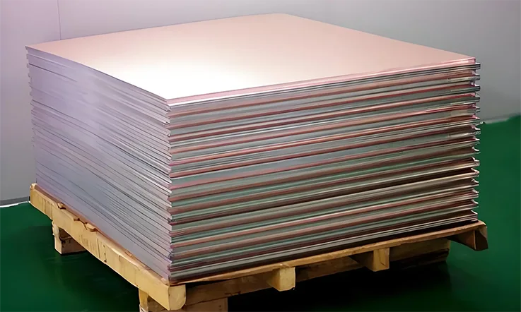
Arlon 49N is a polyimide laminate specifically designed to meet the rigorous demands of high-performance applications in aerospace, military, and high-temperature environments. With its polyimide resin system and glass reinforcement, Arlon 49N offers superior thermal stability, mechanical strength, and reliability, making it a strong contender for designs requiring resilience under extreme conditions.
This laminate material supports both standard and complex PCB manufacturing processes, facilitating precision in intricate designs where performance and durability are non-negotiable. Therefore, if you’re working on RF/microwave circuits, advanced military systems, or other high-stress applications, Arlon 49N helps ensure that your projects meet both performance goals and long-term operational needs.
Why Arlon 49N PCB Is Suitable for Aerospace and Military-Grade Electronics?
Aerospace and military applications often impose extreme mechanical, thermal, and environmental demands on electronic components. In these sectors, PCBs are required to maintain consistent electrical performance, dimensional stability, and long-term mechanical strength under prolonged exposure to elevated temperatures, vibration, and shock. Arlon 49N PCB, manufactured with a modified polyimide resin system, is widely adopted in such environments due to its thermal reliability, structural integrity, and compliance with high-reliability manufacturing standards.
The following sections highlight how Arlon 49N PCB addresses specific challenges in aerospace and defense-grade electronic design.
Polyimide Durability and Flame Resistance for Harsh Environments
The Arlon 49N laminate is formulated using a non-brominated, high-performance polyimide resin system. Its thermal endurance is achieved through a resin-glass matrix that delivers dimensional stability even when exposed to continuous operating temperatures above 200°C. This feature is especially relevant in aerospace electronic assemblies located near propulsion systems or within temperature-sensitive control modules.
Flame retardancy is certified under UL 94 V-0, meeting standard requirements in avionics and aerospace electrical systems. Additionally, its thermal performance minimizes resin degradation over time, ensuring longer operational lifecycles while maintaining signal integrity and substrate strength.
In multi-layer PCBs exposed to harsh altitude and pressure variations, such as flight data recorders or satellite communication modules, Arlon 49N’s low outgassing and reduced hygroscopic expansion contribute to its long-term reliability.
Reliability of Arlon 49N PCB Under Thermal Cycling and Shock
Electronic systems used in military aircraft and aerospace vehicles are frequently subjected to temperature fluctuations, mechanical shocks, and vibration stress. Arlon 49N PCB maintains structural cohesion under thermal cycling due to its low coefficient of thermal expansion (CTE) in both Z-axis and in-plane directions.
This thermal compatibility with copper reduces the risk of microvia failures, delamination, and pad lifting, which are typical failure modes in high-reliability electronics. The resin system demonstrates minimal resin recession after multiple solder reflow cycles, making it suitable for applications that require multiple assembly stages or rework.
Examples: include mission avionics, satellite payloads, and guided munitions control units where Arlon 49N has been validated for maintaining electrical performance even after exposure to over 500 thermal cycles and shock profiles as outlined in IPC-TM-650 test protocols.
Meeting MIL-SPEC and IPC-4101 Class 3 Standards with Arlon 49N
Arlon 49N is engineered to comply with rigorous quality specifications required in the defense sector. It meets the performance requirements for IPC-4101/40, IPC-4101/41, and supports fabrication under IPC-6012 Class 3 and 3A guidelines. These standards are aligned with applications requiring uninterrupted performance and long lifecycle stability, even under adverse mechanical and thermal loads.
Material performance characteristics—such as peel strength, insulation resistance, and solder float stability—have been verified under qualification conditions that simulate operational environments encountered in satellite navigation systems, missile guidance circuits, and aerospace radar assemblies.
For defense OEMs and aerospace contract manufacturers, using Arlon 49N helps streamline qualification procedures due to its traceability, material consistency, and manufacturing predictability. The low Dk drift over frequency and temperature makes it suitable for high-speed digital, mixed-signal, and RF/microwave designs where signal integrity must be maintained across variable load conditions.
Arlon 49N PCB vs Isola, Rogers, Taconic, Teflon, and Other High-Temperature Laminates
Selecting the right laminate material plays a central role in designing high-performance PCBs, especially for applications exposed to elevated temperatures. The material’s thermal properties, mechanical characteristics, and cost efficiency are all factors in determining which option works best for specific needs. Arlon 49N holds its own among other high-temperature laminates like Isola, Rogers, Taconic, and Teflon. Let’s take a closer look at the differences and how each material meets particular demands.
Comparative Thermal Stability and Tg Analysis
Thermal stability, often measured by the glass transition temperature (Tg), is a primary factor when choosing a high-temperature laminate. A higher Tg indicates a material’s capacity to resist heat without altering its structural or electrical properties.
●Arlon 49N has a Tg of 170°C, which suits applications where moderate heat resistance is necessary.
●Rogers 4350B offers a higher Tg of 280°C, providing better performance in high-temperature environments.
●Isola FR408 shares a Tg of 180°C, fitting well into automotive and telecom sectors.
●Taconic TLY offers a Tg of 200°C, which serves high-frequency applications better due to increased heat resistance.
●Teflon shines with a Tg of 327°C, making it suitable for extreme heat applications like aerospace.
| Material | Tg (°C) | Temperature Stability | Common Uses |
| Arlon 49N | 170 | Moderate | Telecom, Industrial |
| Rogers 4350B | 280 | High | Aerospace, Military |
| Isola FR408 | 180 | Moderate | Automotive, Medical |
| Taconic TLY | 200 | High | RF Applications |
| Teflon | 327 | Very High | Aerospace, High-Temp |
Arlon 49N provides reliable thermal stability for standard applications, offering a balance of performance and cost-effectiveness.
Mechanical Strength and Material Flexibility
Mechanical strength is an essential factor for applications that experience stress or thermal cycling. The material must maintain its integrity while supporting the physical demands of the design.
●Arlon 49N offers good strength and flexibility, making it ideal for use in multilayer designs.
●Rogers 4350B is highly rigid, making it better for applications requiring high structural integrity.
●Isola FR408 has good strength, with more flexibility than some high-temperature materials.
●Taconic TLY provides excellent flexibility and thermal expansion resistance, often chosen for rigid-flex designs.
●Teflon, while offering excellent heat resistance, does not provide the same level of mechanical strength as other options.
For designs requiring flexibility, Taconic TLY is a suitable choice, while Rogers 4350B is better for more rigid, high-density PCBs.
Application Suitability: When to Choose Arlon 49N PCB
Arlon 49N is well-suited for a variety of applications requiring a balanced approach to thermal and mechanical performance, without the need for extreme specifications.
When to consider Arlon 49N-
●Telecommunications: Provides a solid mix of thermal stability and electrical performance, making it suitable for RF and high-speed digital circuits.
●Automotive and Industrial: With its moderate thermal resistance, Arlon 49N works well for applications that don’t require extreme temperature endurance but still demand consistent performance.
●Aerospace: Though Rogers 4350B may be favored for the most challenging high-temperature applications, Arlon 49N offers a practical, cost-efficient alternative.
●Medical Devices: Arlon 49N’s low moisture absorption and steady electrical properties make it suitable for medical electronics without the need for extreme heat handling.
When to consider other materials-
●Rogers 4350B: Best for high-performance applications with demanding thermal stability requirements.
●Taconic TLY: It good for applications requiring high flexibility and resistance to thermal expansion, especially in flexible circuit designs.
●Teflon: The material of choice for extreme temperature applications such as aerospace and other high-demand environments
Electrical Performance of Arlon 49N PCB in High-Frequency and RF Applications
In high-frequency and RF applications, reliable signal integrity, minimal power loss, and consistent impedance are necessary for the effective performance of communication systems. Arlon 49N PCB, made with a polyimide resin system and engineered glass fabric, is built to meet the strict demands of aerospace, military, and RF communication systems. Its exceptional electrical properties and structural strength ensure steady signal transmission in high-speed and RF applications.
Designing PCBs for high-frequency systems—such as radar, satellite communication, and RF-based systems—requires careful selection of materials that offer reliable electrical properties with minimal signal degradation. Arlon 49N delivers on these demands by maintaining strong performance under challenging environmental conditions.
Let’s explore how Arlon 49N excels in providing solutions for high-frequency applications.
Low Dissipation Factor and Stable Dielectric Constant
Arlon 49N demonstrates a remarkably low dissipation factor (Df)—approximately 0.022 at 1 MHz—which directly contributes to reduced power loss. This is especially valuable in high-frequency and microwave applications, where heat generated from power loss can significantly impact system performance.
Additionally, Arlon 49N maintains a dielectric constant (Dk) of approximately 4.3, ensuring the consistency of signal transmission even at frequencies up to 1MHz. This stable Dk is particularly beneficial for high-speed digital circuits and RF signals, which require minimal variations to maintain signal quality over long distances or in high-frequency conditions.
For instance, in satellite communication systems where timing precision is necessary, the low Df and stable Dk of Arlon 49N allow us to design circuits that offer consistent performance across varying conditions.
If you are working with RF applications, consider materials like Arlon 49N to ensure minimized signal degradation.
RF/Microwave Signal Integrity in Arlon 49N PCB Stack-Ups
Signal integrity is a top concern in RF and microwave applications, where even slight distortions can compromise performance. To mitigate this, careful design of PCB stack-ups is essential. Arlon 49N’s combination of thermal and electrical stability is well-suited for constructing multi-layer PCB stack-ups, ensuring that signal transmission remains stable and uninterrupted.
The low coefficient of thermal expansion (CTE) and z-axis stability of Arlon 49N ensures that the layers remain aligned during manufacturing, even with temperature fluctuations. This characteristic helps preserve signal integrity in high-frequency circuits, such as those used in radar systems, phased array antennas, and GPS devices.
For example, in radar applications, where precise signal timing is necessary, Arlon 49N’s stable properties prevent issues like signal reflection and crosstalk, which can distort signals and degrade system performance.
For more reliable microwave circuit designs, Arlon 49N guarantees consistent layer-to-layer electrical performance.
EMI Control and Controlled Impedance Routing
In RF designs, controlling electromagnetic interference (EMI) helps preserve signal clarity. This is particularly true in multi-layer PCB designs, where sensitive RF signals could potentially interact with noisy power or ground planes. Arlon 49N’s controlled dielectric constant and uniform glass fabric distribution enable the creation of controlled impedance routes that reduce signal loss and minimize EMI.
For RF/microwave designs, particularly those requiring 50-ohm or 75-ohm traces, Arlon 49N provides a reliable base material that supports the precision needed for consistent impedance. For example, in systems like 5G networks or satellite communications, maintaining a consistent impedance profile ensures that signals travel without distortion or reflection loss, leading to better performance.
Moreover, its low moisture absorption rate (less than 0.2%) makes Arlon 49N suitable for outdoor applications, where long-term exposure to environmental conditions could otherwise affect signal integrity.
If you need precise impedance control for your RF circuits, Arlon 49N helps maintain signal integrity while minimizing EMI and reflection loss.
Advanced Stack-Up Design with Arlon 49N PCB for Multilayer and HDI Boards
Designing complex stack-ups for high-density interconnect (HDI) and multilayer applications takes more than just layering materials—it’s an exercise in precision, material understanding, and long-term stability. Arlon 49N PCB material, built on a heat-resistant polyimide resin system with tailored glass fabric reinforcement, fits snugly into the demands of next-gen communication platforms, aerospace signal modules, and dense military radar assemblies. As its thermal reliability, electrical consistency, and mechanical durability, Arlon 49N supports tight stack-up configurations that accommodate blind vias, buried structures, and signal isolation layers—without cracking under pressure.
If you’re dealing with 10+ layer boards or dense via-in-pad designs, it’s time to look under the hood and see how Arlon 49N can give you a layout strategy that’s built to last.
Core/Prepreg Pairing and Cross-Section Control
When it comes to keeping stack-up geometry in check, the way cores and prepregs are paired can make or break your cross-sectional balance. Arlon 49N PCB materials come with a selection of polyimide-based cores and compatible prepregs engineered to reduce resin starvation, fiber weave distortion, and thickness variation—all of which can throw your impedance and mechanical tolerance out of spec.
Our design engineers leveraging Arlon 49N for HDI or defense-grade systems often pair 5-mil cores with prepregs that offer consistent resin flow and glass transition alignment. This tight pairing prevents resin-rich or resin-starved zones that tend to emerge during press cycles, especially when layer counts climb north of 12.
Sticking to uniform thicknesses across each dielectric interval, especially when building up mixed-layer stack-ups with RF signal routing or embedded power planes, ensures clean processing at every stage—from lamination to laser via formation.
Table: Core/Prepreg Pairing Options for Arlon 49N PCB:
| Core Thickness | Prepreg Type | Resin Flow Characteristics | Application |
| 5 mils | Arlon 49N Prepreg 1 | Consistent Resin Flow | HDI, Defense-grade Systems |
| 10 mils | Arlon 49N Prepreg 2 | Low Shrinkage and Uniformity | RF Signal Routing, High Layer Count |
| 15 mils | Arlon 49N Prepreg 3 | Balanced Resin Distribution | Power Planes, Complex Stack-ups |
Blind and Buried Via Optimization for Arlon 49N
High-density interconnect designs often rely on blind and buried vias to squeeze signal routing into compact form factors without stacking everything through-hole. Here’s the rub: blind and buried vias stress materials more than standard drills, especially when thermal cycles and reflow hits come into play. Arlon 49N’s low z-axis expansion keeps these vias aligned and structurally intact across repeated thermal shocks.
Its resin system handles laser-drilled microvias with precision and keeps smear and delamination risks low during desmear and plating. That’s especially helpful when designing via-in-pad configurations for radar front-ends or high-speed transceivers in defense gear.
Table: Via Optimization for Arlon 49N PCB:
| Via Type | Z-Axis Expansion | Thermal Cycle Resistance | Laser Drilling Suitability |
| Blind Via | Low Expansion | Excellent (1000+ cycles) | Optimal |
| Buried Via | Low Expansion | High Resistance | Suitable |
| Microvia | Minimal Expansion | High Reliability | Highly Suitable |
Want better plating reliability and lower risk of barrel cracking after 1000+ thermal cycles? You’re in safe hands with Arlon 49N when your design pushes the limits of via density.
Signal Layer Isolation and Power Integrity Best Practices
Power integrity doesn’t happen by accident—it’s a product of smart layer stacking, signal zoning, and tight reference plane design. Arlon 49N’s stable dielectric properties (Dk ~4.3 at 1MHz) and low dissipation factor (Df ~0.022 at 1MHz) allow signal layers to operate without cross-coupling or impedance drift, even when packed next to noisy power traces.
Using Arlon 49N in combination with symmetrical ground plane placements helps maintain power rail stability across multi-GHz switching speeds. Engineers designing satellite RF modules or embedded digital processors for avionics often separate digital, analog, and RF zones into isolated pockets—keeping return paths tight and EMI under control.
Its low moisture absorption also guards against unpredictable impedance drift due to humidity, a factor not to be ignored when boards are deployed in outdoor or airborne conditions.
Table: Signal Integrity and Power Isolation with Arlon 49N PCB
| Layer Type | Dielectric Constant (Dk @1MHz) | Dissipation Factor (Df@1MHz) | Moisture Absorption | Application |
| Signal Layer | 4.3 | 0.022 | Low | RF, High-Speed Digital Circuits |
| Power Plane | 4.3 | 0.022 | Very Low | Aerospace, Satellite Modules |
| Ground Plane | 4.3 | 0.022 | Minimal | Military Systems, Avionics |
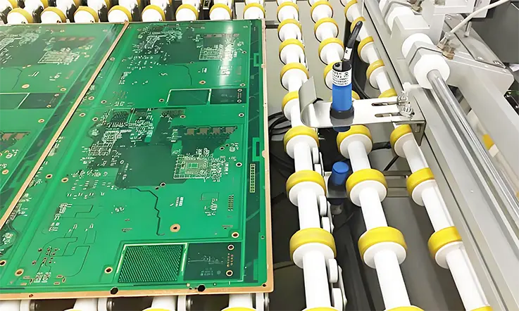
Manufacturing Considerations for Arlon 49N PCB in High-Precision PCB Fabrication
When working with Arlon 49N PCB material in high-precision circuit board fabrication, each stage plays a role—from prepreg stack-up to final surface finish. Its polyimide resin system and woven glass construction require careful attention to fabrication conditions, especially for aerospace, RF/microwave, and rugged military applications. When done correctly, the material provides tight dimensional control, thermal stability, and reliable performance. Achieving this requires precise process adjustments and focus on details.
Lamination Cycles and Resin Flow Management
Unlike traditional FR-4, Arlon 49N runs on a polyimide resin system that needs a little more TLC during lamination. Its cure profile demands higher temperatures, typically between 218°C and 227°C, with controlled ramp rates to avoid stressing the resin or glass fabric. Rushing through this step risks voids, poor bond lines, or uneven fill—especially around via clusters or plated cavity structures.
Prepreg layout influences uniform fill across the panel. Over-packing the stack-up with resin-heavy layers can lead to flow imbalances. Under-packing it may cause starvation in dense copper areas. A common solution is to include flow channels or vent structures to balance the distribution, particularly during sequential lamination cycles often used in HDI builds.
Pressure settings also deserve close attention. Pressing too hard risks glass weave shift or corner bleed-out, particularly along outer layer edges. Keeping the pressure around 275–350 psi typically holds the line without introducing new headaches.
Drilling Parameters and Hole Wall Integrity
Drill-time decisions can make or break plating quality later on. Arlon 49N’s high Tg (250°C+) and low Z-axis expansion give it strong dimensional control during thermal excursions—but that doesn’t make it immune to poor drill recipes. This stuff’s tougher than your average board, and it needs sharper bits and tighter controls.
To avoid resin smear or glass push-out, stick to entry/exit materials designed for polyimides. Keep chip load between 1.5 to 2.0 mils/rev, and limit bit life to no more than 800 hits. Peck cycles and retract rates should be tuned to minimize heat buildup while maintaining hole accuracy. Especially for vias under 0.3mm, it’s a good idea to laser drill first, then clean up with mechanical backdrills if needed.
Got stacked vias or microvias? Use step drilling or hybrid methods to keep the drill from wandering or chipping copper pads on inner layers.
Solder Mask, Copper Foil, and Surface Finish Compatibility
Arlon 49N’s polyimide chemistry resists thermal shock, which is great for lead-free soldering or high-reflow temps—but don’t let that fool you into thinking all masks or finishes will behave the same.
Standard LPI masks may not grab onto polyimide the way they do with epoxy-based materials. For better adhesion, opt for high-performance mask formulas rated above 245°C. Also, don’t forget pre-bake steps—Arlon 49N’s low moisture absorption (<0.2%) helps, but trapped humidity is still a risk on fine-line HDI jobs.
When choosing copper foils, both rolled annealed and reverse-treated options are available. Rolled foils offer smoother profiles, which help with fine-line etching and impedance control. Reverse-treated foil, meanwhile, may improve peel strength but could affect etch uniformity, especially in sub-6 mil trace designs.
Surface finish selection depends on your design goals. ENIG works well for mixed-signal boards, while immersion silver offers better performance in low-loss RF applications. Just make sure your finish is process-compatible with Arlon’s thermal behavior—and don’t skip bake cycles prior to finishing.
Fabrication Best Practices for Reliable Arlon 49N PCB Production
In high-precision PCB manufacturing, handling Arlon 49N laminates requires meticulous attention to detail. From storage to post-lamination inspection, each phase influences the board’s performance and longevity. Let’s delve into the essential practices that ensure your Arlon 49N PCBs meet the highest standards
Moisture Baking, Storage, and Handling Conditions
Arlon 49N’s polyimide composition, while offering superior thermal stability, is susceptible to moisture absorption if not managed properly. Excessive moisture can lead to defects like delamination or blistering during soldering.
Storage Recommendations-
●Environment: Store PCBs in a controlled setting with relative humidity (RH) below 50% and temperature around 25°C.
●Packaging: Utilize Moisture Barrier Bags (MBBs) with desiccants and Humidity Indicator Cards (HICs) to monitor internal conditions.
Handling Practices-
●Post-Bake Timing: After baking, proceed with assembly promptly, ideally within 24 hours, to minimize moisture reabsorption.
●Environmental Exposure: Limit PCB exposure to open air, especially in high-humidity environments, to prevent moisture ingress.
Pre-Drill Bake and De-Smear Requirements
Before drilling, it’s imperative to ensure that Arlon 49N laminates are devoid of moisture to prevent defects like resin smear or delamination.
Pre-Drill Baking-
●Temperature and Duration: Bake PCBs at 125°C ±5°C for 4–6 hours, depending on board thickness and storage conditions.
●Cooling: Allow boards to cool in a controlled environment to room temperature before proceeding.
De-Smear Process-
Post-drilling, the de-smear step ensures resin residues are removed, allowing for reliable electrical connections.
●Plasma or Chemical Methods: Choose an appropriate de-smear technique compatible with polyimide materials to clean hole walls effectively.
●Process Control: Monitor parameters like exposure time and chemical concentrations to avoid over-etching or damage.
Post-Lamination QA and Microsection Analysis
After lamination, rigorous quality assurance (QA) ensures the structural integrity and performance of Arlon 49N PCBs.
Visual Inspection-
Surface Examination: Check for external defects such as blisters, delamination, or misalignment.
Microsection Analysis-
This analytical technique provides an internal view of the PCB’s cross-section, revealing insights into:
●Layer Adhesion: Assess the bond quality between laminated layers.
●Hole Wall Integrity: Evaluate the effectiveness of drilling and de-smear processes.
●Copper Plating Thickness: Measure to ensure compliance with design specifications.
Process Documentation-
●Record Keeping: Maintain detailed logs of inspection results to trace and address potential issues in future production runs.
By implementing these practices, we can enhance the reliability and performance of Arlon 49N PCBs. Attention to storage, handling, and thorough post-lamination inspections are not just recommendations—they’re the benchmarks for excellence in PCB fabrication.
How PCB Designers Can Optimize Layout for Arlon 49N PCB Material?
When working with Arlon 49N in advanced RF or aerospace-grade PCB layouts, successful signal routing and thermal balance often begin at the drawing board—literally. This polyimide-based laminate offers low dissipation factor and consistent dielectric properties, but dialing in performance requires more than just good CAD skills. From stack-up planning to trace tuning and power distribution, layout practices need to reflect the behavior of the material under high-frequency load, high current, and thermal cycling.
Let’s break it down by layout domain, and show how a few front-end decisions can save you from chasing headaches at the fab shop or in post-build debug.
Layer Planning and Isolation Rules
Multilayer stack-ups using Arlon 49N benefit from tight dielectric control, but that advantage only pays off when signal layers are properly isolated. Adjacent layers carrying mismatched signals—like high-speed RF on one and switching power on the next—can create unintended coupling. To avoid that mess, alternate signal and reference planes with consistent copper return paths.
Also, watch your spacing when using Arlon 49N in hybrid stack-ups. If you’re pairing it with other polyimide or PTFE-based laminates, the prepreg flow and z-axis expansion need to be coordinated. Without that, differential expansion can skew impedance and skew layer registration. Here’s a quick layout reference:
| Layer Function | Recommended Isolation Strategy | Dielectric Thickness (mm) |
| RF Signal | Ground plane underlayer | 0.20–0.28 |
| Digital Logic | Power plane shield | 0.13–0.18 |
| Clock/Timing | Split reference zone | 0.18–0.22 |
Tip: Maintain uniform copper balancing in outer layers to avoid warpage post-etch. Arlon 49N’s low z-axis CTE helps, but only if the copper layout plays ball.
Trace Width and Spacing for Controlled Impedance
Arlon 49N shows consistent Dk across temperature swings and frequencies up to 10 GHz, making it a strong option for high-speed controlled impedance traces. However, polyimide substrates tend to shift less under thermal stress, so your trace width-to-height ratio becomes more significant.
For 50-ohm microstrip lines, trace widths typically fall between 9–11 mils on 0.2 mm cores. Stripline configs in buried layers can drop that to 6–8 mils depending on the prepreg height. Be sure to calculate with the actual copper foil thickness after plating—reverse-treated or rolled-annealed copper both influence impedance differently.
Here’s a simplified impedance tuning cheat sheet:
| Stack Type | Trace Width (mil) | Dielectric Height (mm) | Expected Impedance (Ω) |
| Microstrip | 10 | 0.20 | 50 |
| Stripline | 8 | 0.18 | 50 |
| Differential Pair | 6 (each) | 0.15 | 100 (±10%) |
Use length tuning and staggered ground stitching vias to balance paired signals, especially on differential lines crossing split planes.
High-Current Power Plane Design Considerations
For high-current zones, such as those found in phased arrays or motor control circuits, Arlon 49N can support thicker copper planes without breaking alignment. Its polyimide matrix resists resin cracking during thermal rise, allowing you to push 2 oz or even 3 oz copper on interior layers—if your press cycles are dialed in.
But don’t just throw copper at it. Use polygon pours with defined via arrays to manage IR drops and ensure even heat dissipation. Also, keep power planes isolated from sensitive analog signal lines. The polyimide core won’t provide noise rejection automatically—layout discipline is still necessary.
A good rule of thumb:
●Use via stitching every 0.5 inches along high-current paths.
●Separate analog and digital power by at least 2 dielectric layers.
●Create thermal reliefs to prevent etch bottlenecks in dense copper pours.
Why Signal Integrity Design Using Arlon 49N PCB in High-Speed Digital Circuits?
When working with high-speed digital systems, the layout must reflect a deep understanding of signal behavior. In systems where timing margins are tight and signal degradation is a concern, selecting the right material becomes a foundational choice. Arlon 49N, with its low-loss polyimide resin and controlled Dk/Df properties, offers a solid base for achieving high-performance designs where clean transitions and stable impedance are required.
However, choosing the right material is only part of the equation. The success of signal integrity hinges on how the layout is executed. Matching the behavior of the substrate with the appropriate routing strategy can make a significant difference. Let’s explore how this combination helps high-speed circuits maintain the level of performance and reliability needed in today’s designs.
Crosstalk and Propagation Delay Reduction
The dielectric constant of Arlon 49N (approximately 3.8 at 10GHz) helps maintain consistent delay times within an acceptable range. However, it doesn’t eliminate the risk of crosstalk between traces. Effective routing requires careful attention to spacing, reference plane management, and ensuring proper return paths.
●Recommended trace-to-trace spacing: 4W for outer layers, 3W for inner layers
●Propagation delay: ~145 ps/inch @ 50Ω, depending on stack-up
●Insertion loss improvement: ~20–25% compared to FR-4 in the 5–10 GHz range (based on stripline measurements)
| Trace Width (50Ω) | Arlon 49N (Inner Layer) | Arlon 49N (Outer Layer) |
| 4-mil core | ~8.5 mils | ~10.3 mils |
| 6-mil core | ~11.7 mils | ~13.5 mils |
To minimize crosstalk, place aggressive lines on different layers, ensuring they’re separated by solid reference planes. Avoid stub routing, which can be a source of noise above 4 GHz.
PCB Routing Guidelines for Low Jitter Performance
Jitter can disrupt timing on high-speed serial interfaces or clock trees, and routing choices have a large impact on how much jitter is present in a design. The low dissipation factor of Arlon 49N (~0.005) helps keep phase noise under control, but it’s up to the routing layout to handle the rest.
Here’s what to keep in mind:
●Avoid sharp corners—Use mitered 45° bends or smooth curves
●Maintain consistent impedance—Differential pairs should match within ±10%
●Limit layer transitions—Every via adds complexity to the signal path
Differential pair tuning is essential for minimizing jitter. On Arlon 49N, 100Ω differential pairs can be tuned using ~4.8 mil traces on a 4-mil core with 5.5–6.5 mil spacing. Proper tuning prevents impedance mismatch and keeps jitter within expected levels.
Quick tip: When working on PCIe Gen4/Gen5, use backdrilled vias to minimize signal degradation and limit skew to under 5 mils per pair.
Via Design and Layer Transition Optimization
The effectiveness of vias on Arlon 49N comes down to the specific design choices made during layout. While Arlon 49N provides excellent thermal stability and minimal Z-axis expansion, improper via transitions can create unwanted reflections.
●Use shorter via stubs for frequencies over 6 GHz—keep them under 15 mils
●Adjust via pad sizes for smooth transitions between microstrip and stripline
●Consider backdrilling for high-speed signals to eliminate stub-related impedance mismatches
●Use via fences—place ground vias around signal vias to improve isolation
| Design Element | Standard FR-4 | Arlon 49N (Optimized) |
| Via Stub Length | < 20 mils | < 10 mils |
| Via Annular Ring | ≥ 5 mils | ≥ 6 mils |
| Via Pad to Anti-pad | ≥ 12 mils | ≥ 14 mils |
Heads-up: For designs like 10GBASE-KR or USB4, consider using via-in-pad with epoxy fill and planarization on Arlon 49N to minimize reflections and achieve higher signal integrity.
Procurement and Sourcing Guide for Arlon 49N PCB Material
Sourcing Arlon 49N for your multilayer RF or high-temperature polyimide builds involves more than just calling up your usual vendor. Given the material’s resin system and thermal characteristics, manufacturers need to align their sourcing game with both electrical performance targets and production floor realities. From global supplier networks to prepreg thickness control and lot consistency, there’s a lot that can throw your schedule out of whack—unless you’re planning with the right info up front.
Preferred ARLON Distributors and Availability Worldwide
Arlon 49N is distributed globally through authorized channels such as Rogers Corporation’s regional partners and vetted specialty laminate suppliers. While availability in North America and Europe remains stable for standard sheet sizes, sourcing in Southeast Asia or Eastern Europe may require added lead time or coordination with local stocking reps.
Below is a reference table for select distributors handling Arlon 49N globally:
| Region | Distributor Partner | Typical Lead Time | Notes |
| North America | Insulectro, RFMW | 2–4 weeks | Common builds in stock |
| Europe | Adeon, Elmatica | 3–5 weeks | Regional stocking varies |
| Asia-Pacific | WKK, Ventec (via Rogers) | 4–6 weeks | Coordinate with plant-level logistics |
| Middle East | ACB, Avnet (limited) | 6+ weeks | Often project-specific ordering only |
Prepreg and Core Thickness Options for Arlon 49N PCB
To match stack-up requirements in RF, HDI, or thermal-cycling environments, Arlon 49N comes in a range of standard and custom thicknesses. The prepreg typically uses E-glass styles (2116, 106, 1080) with resin content between 38%–52%. Cores are available in thicknesses ranging from 0.002” to 0.125”, allowing you to hit specific impedance and total thickness targets.
Here’s a summary table:
| Type | Thickness Range | Typical Application |
| Prepreg | 0.0015″–0.006″ | Interlayer bonding for HDI, RF builds |
| Core | 0.002″–0.125″ | Ground planes, signal layers, backbones |
| Hybrid | Custom stack-ups | Mixed-material systems (e.g., FR-4/49N) |
Need to fit into a tight Z-stack height or dial in capacitance? Arlon 49N’s layering options give us some leeway—just don’t forget to spec out copper thicknesses in your drawings.
Thinking about high-speed signal control? Consider pairing 0.005″ cores with 0.0015″ prepreg for low-loss, fine-pitch RF stack-ups.
Managing Lead Times, Batch Quality, and Certifications
Consistency is necessary when fabricators are working to meet Class 3 or space/aero-grade specs. For Arlon 49N, Rogers Corporation provides lot-to-lot traceability and IPC-4101/40 compliance, but procurement teams still need to watch for potential shifts in resin flow or glass weave alignment between runs.
Here’s what seasoned sourcing teams keep on the radar:
●Lead Times: For large-volume orders or custom-cut panels, expect 6–8 weeks from Rogers direct or 4–5 weeks via stocking reps.
●Certs to Request: IPC-4101/40, UL 94V-0, RoHS, REACH, and AS9100 batch lot traceability.
●Inspection Advice: Ask for recent Tg and Dk lab data per lot—don’t assume prior values match the current batch.
Cost Efficiency and Value Engineering with Arlon 49N PCB
When evaluating PCB materials for high-frequency, aerospace, or defense systems, it’s easy to get tunnel vision on unit pricing. But when it comes to Arlon 49N, looking at cost only from the front-end misses the bigger picture. This polyimide-based laminate, known for its thermal stability and dielectric consistency, brings more to the table over time—especially in harsh environments where long-term reliability can save rework, field returns, and schedule blowouts.
Smart layout planning, paired with tight process control, can squeeze more value out of every panel. If you’re sourcing for high-layer-count or hybrid builds, keep reading—there’s money on the table, and we’re about to show you how to grab it.
Lifecycle Cost vs Initial Material Cost
It’s tempting to go for the lowest per-sheet price, but with Arlon 49N, that mindset can backfire in high-reliability applications. The material’s high Tg, low CTE, and predictable loss behavior can help cut down on re-spins, delamination incidents, and signal degradation—especially in boards exposed to thermal cycling or shock.
| Factor | FR-4 Stackup | Arlon 49N Stackup |
| Initial Material Cost | Low | Higher |
| Copper Plating Uniformity | Variable | Stable |
| Thermal Cycle Tolerance | Moderate | Excellent |
| Rework/Failure Rate (Est.) | 8–12% | <3% |
| Average Lifetime per System | ~5 years | 8–10 years |
Paying a bit more upfront for Arlon 49N can save thousands in requalification and rework during a product’s lifecycle—especially in rugged sectors like defense comms or high-altitude avionics.
Yield Optimization in Multilayer Stackups
Yields are a core factor—especially when layer counts exceed 12 or stackups become dense with buried vias, cavity structures, or mixed-dielectric zones. Arlon 49N, with its low Z-axis expansion and low resin shrinkage during cure, performs well in sequential lamination builds. However, yield is influenced by prepreg flow tuning, foil pairing, and lamination strategy.
Here’s what you’ll want to keep on your radar:
●Prepreg Selection: Use consistent resin content across builds to avoid flow imbalance. For 49N, a 43–46% resin content range works well across 106, 1080, and 2116 glass styles.
●Buried/Blind Via Strategy: Stick to microvia ≤0.15 mm and avoid overstacking. Use staggered layouts to prevent resin starvation or delam at the base.
●De-smear Settings: Optimize plasma or permanganate settings based on the actual stack-up thickness. Arlon 49N tolerates higher temperatures but still needs clean hole walls for high copper wrap.
Frequently Asked Questions About Arlon 49N PCB
1.What types of PCB designs benefit most from Arlon 49N material?
High-performance, high-temperature, and high-reliability designs, especially in aerospace, military, and RF/microwave circuits.
2.Can Arlon 49N be used in high-precision military electronics?
Yes, Arlon 49N is well-suited for high-precision military electronics due to its thermal stability and mechanical robustness.
3.What is the minimum trace width and spacing for Arlon 49N?
The minimum trace width and spacing will depend on the specific design requirements, but a common guideline is 4 mils for trace width and 4 mils for spacing.
4.What are the drill hole recommendations for Arlon 49N?
For optimal hole wall integrity, it’s recommended to use a drill bit with a diameter of at least 0.25 mm, and to control the drill speed to avoid excessive heat buildup.
5.What are the prepreg and core thickness options for Arlon 49N?
Prepreg and core thicknesses typically range from 0.002″ to 0.062″ and can be customized to meet specific design requirements.
6.What is the peel strength of Arlon 49N?
Arlon 49N typically offers a peel strength of 3-5 lb/in, which ensures reliable bonding of copper to the substrate during PCB manufacturing.
7.What is the recommended storage condition for Arlon 49N?
Arlon 49N should be stored in a cool, dry environment at temperatures between 18°C and 25°C (65°F and 77°F) to prevent degradation and moisture absorption.
Our services
Arlon PCB Laminate & Materials Series