The design and manufacturing of 6-layer PCBs (Printed Circuit Boards) require a high level of technical expertise and careful consideration at every stage of the process. These multi-layer boards are essential for applications that demand compact size, advanced functionality, and enhanced performance. From consumer electronics to medical devices, telecommunications, and automotive systems, 6-layer PCBs support complex circuit designs that ensure optimal signal integrity and power management.
In this guide, we will explore the key aspects of 6-layer PCB design, manufacturing capabilities, and cost considerations, offering insights into how these factors impact both the design process and the final product. By understanding these elements, we can ensure that our 6-layer PCBs are both high-performing and cost-efficient.
Understanding the 6-Layer PCB Design Process
As technology continues to advance, 6-layer PCBs have gained widespread adoption for enabling high-performance, compact designs in various modern devices. These PCBs are a vital part of systems that require high-speed signal integrity, efficient thermal management, and stable performance in demanding applications. Devices like smartphones, medical electronics, and 5G infrastructure heavily rely on 6-layer PCBs for their ability to manage complex circuits and high-frequency signals.
In this section, we will explore the design process of a 6-layer PCB, examining the structure and stack-up configuration, while also highlighting some of the common challenges we face when working with these advanced boards.
What is a 6-Layer PCB and Why Is It Needed in Modern Electronics?
A 6-layer PCB consists of six individual layers of conductive material, each with its own function within the circuit design. The board’s layout is usually as follows:
●Outer layers (Layer 1 and Layer 6) are responsible for routing the high-frequency signals and connecting the components.
●Inner layers (Layer 2 to Layer 5) provide space for power distribution, signal routing, and ground planes, all of which help reduce signal interference and ensure the proper flow of current.
This type of structure is commonly used in applications that demand careful signal handling and circuit stability, such as 5G technology, smartphones, and medical devices.
Applications of 6-Layer PCBs-
●Smartphones: Thanks to the layered structure of 6-layer PCBs, smartphones can pack more components into smaller spaces without sacrificing the performance of their circuits.
●Medical Devices: Devices that rely on precision and consistent performance, like heart rate monitors and medical imaging equipment, often use 6-layer PCBs to meet the strict performance needs in these fields.
●5G Networks: The development of 5G infrastructure benefits from 6-layer PCBs, which are capable of handling the high-speed data transmission required for next-gen telecommunication networks.
Key Design Principles in 6-Layer PCB Engineering
Designing a 6-layer PCB requires adherence to several principles to ensure that the board performs reliably and efficiently:
●Signal Integrity and Impedance Control: High-frequency signals are susceptible to distortion and loss if not properly routed. To maintain clarity, we use controlled impedance and differential pair routing to preserve signal quality across the board.
●Thermal Management: Managing heat distribution within a 6-layer PCB helps preserve the longevity of its components. By integrating thermal vias and ground planes, heat is spread evenly across the board, keeping temperatures within safe ranges. This approach ensures that the board continues to perform as intended, reducing the risk of overheating and damage to sensitive parts.
●Power Distribution Networks (PDNs): A well-designed power distribution network ensures that each component receives a stable supply of power, minimizing voltage drops and reducing electrical noise. This is particularly useful in preventing instability during high-demand operations.
Common Design Challenges in 6-Layer PCBs and Solutions
Although 6-layer PCBs offer numerous advantages, we must overcome a set of specific challenges to guarantee that the boards function as intended. By addressing these challenges during the design phase, we can optimize performance and avoid potential issues later in the production process.
●Signal Crosstalk: Signal interference between traces on adjacent layers, or crosstalk, can degrade data transmission. To minimize this issue, we use ground planes between signal layers, effectively shielding and isolating the signals for better clarity.
●Power Noise: Electrical noise can disrupt the operation of sensitive components, leading to performance issues. Techniques such as adding decoupling capacitors, employing multiple ground planes, and separating power planes help mitigate power noise and ensure a stable power supply.
●Thermal Management: When dealing with high-speed circuits, managing heat is a factor in ensuring reliable performance. We use thermal vias and heat spreaders to distribute heat more evenly, reducing the risk of hot spots that could cause damage or lead to performance issues over time.
Manufacturing 6-Layer PCBs: Techniques and Considerations for High-Quality Production
Manufacturing a 6-layer PCB requires more than just the assembly of components on a board—it involves a highly detailed and methodical process to ensure the precision and reliability of the final product. Multilayer PCBs like the 6-layer configuration are used in high-performance devices where every layer must be meticulously crafted and aligned to meet quality standards.
In this section, we’ll take a deep dive into the step-by-step process of 6-layer PCB fabrication, explore the material selection that plays a role in the performance of these boards, and discuss advanced techniques used to improve the overall signal integrity and density of the PCB.
Step-by-Step Process of 6-Layer PCB Fabrication
The fabrication of a 6-layer PCB involves several stages, each requiring careful attention to detail. Let’s walk through the process from start to finish:
1.Layer Preparation: Each of the six layers begins as a thin sheet of copper foil. These sheets are cleaned and prepared to form the required conductive traces. The outer layers are often covered with a soldermask to protect the copper during manufacturing.
2.Layer Lamination: After the copper layers are prepared, the next step is lamination, where the layers are stacked and bonded together under high heat and pressure. This process ensures the layers are fused, forming a solid multilayer structure.
3.Drilling and Via Formation: Once the layers are laminated, precise drilling is performed to create the necessary vias that connect the layers. This is done using laser drills or mechanical drills, and the type of via (blind, buried, or through-hole) is determined based on the design and performance requirements of the PCB.
4.Layer Alignment and Registration: One of the main steps is ensuring that all layers are perfectly aligned. Layer misalignment can lead to defects such as poor signal routing and misconnected traces. Our PCB engineers use advanced registration techniques and automated alignment systems to ensure that all layers are aligned with sub-millimeter precision.
5.Etching: After drilling, the exposed copper is etched away to create the desired circuit patterns on each layer. This step is necessary for signal routing and needs to be done with care to ensure the signal traces maintain their integrity and proper width.
6.Final Finishing: After all layers are etched and vias are formed, the board undergoes final finishing, which includes applying the soldermask, silkscreen, and surface finish such as HASL (Hot Air Solder Leveling) or ENIG (Electroless Nickel/Immersion Gold). This helps protect the PCB and prepare it for component mounting.
Key Considerations in Choosing Materials for 6-Layer PCBs
The materials selected for a 6-layer PCB can greatly influence its performance, signal integrity, and overall reliability. Let’s take a look at some material options and what factors to consider when choosing the right ones for your design:
1.FR4: This is the most common material for 6-layer PCBs, as it provides a good balance between performance and cost. FR4 is suitable for most standard applications but may not perform as well in high-frequency or high-speed designs.
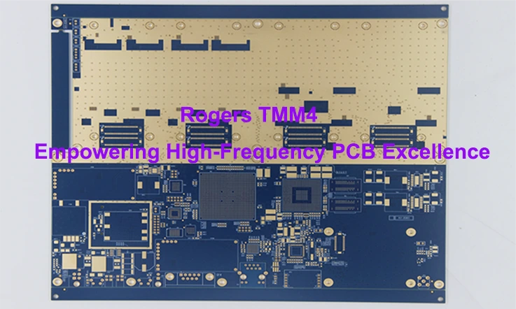
2.High-Frequency Laminates: For designs that demand better performance at higher frequencies (such as 5G, Wi-Fi, or medical devices), high-frequency laminates like PTFE (Teflon) or ceramic-based materials can offer much better signal transmission and lower loss. These materials are more expensive but are necessary for designs where signal degradation cannot be tolerated.
3.Ceramic Substrates: In certain high-power or high-speed applications, ceramic PCBs may be required. These materials offer superior thermal conductivity and are often used in high-performance computing and medical electronics.
Material Choices and Impact on Performance-
| Material Type | Applications | Key Benefits |
| FR4 | General consumer electronics | Affordable, widely available, reliable for low-to-medium frequencies |
| High-Frequency Laminates | 5G, RF, communications | Low signal loss, excellent high-frequency performance |
| Ceramic Substrates | Medical, Aerospace | High thermal conductivity, stable at extreme temperatures |
The material chosen for a 6-layer PCB affects thermal performance, signal quality, and overall reliability. Therefore, selecting the right material helps ensure that the board meets the performance needs of the product.
Advanced Techniques in Via Design for 6-Layer PCBs
The design of vias influences the integrity and performance of a 6-layer PCB. Let’s explore the different via types used and how they affect signal quality and PCB density:
1.Blind Vias: Blind vias connect the outer layers of the PCB to one or more inner layers, but do not go all the way through the board. These vias are often used when the routing of signals needs to be contained within specific layers, allowing for more complex and dense designs.
2.Buried Vias: Buried vias are located only between the inner layers of the PCB and are not visible from the outer layers. They are useful for designs that require high-density routing without sacrificing the outer surface area for signal traces.
3.Microvias: Microvias are extremely small vias (typically less than 150 microns in diameter) that are often used in high-density interconnect (HDI) designs. These vias are typically drilled using laser technology and allow for more compact and complex circuit designs.
Via Design Impact on Signal Quality and Density-
●Blind and Buried Vias help to improve the signal integrity by reducing the number of visible vias on the outer layers, which can reduce the risk of signal degradation.
●Microvias are especially useful in high-density designs where space constraints demand smaller vias that can be placed closer together.
By carefully choosing the right via type for specific applications, we can maximize the signal integrity and density of the PCB while ensuring that high-frequency signals are routed with minimal degradation.
Testing and Quality Control for 6-Layer PCBs: Ensuring Reliability and Performance
As electronics continue to push the envelope of performance, the role of 6-layer PCBs in supporting advanced designs has become even more prominent. These circuit boards serve various applications where both signal integrity and thermal management are central to functionality.
In this section, we’ll walk through the essential testing methods, standards for quality assurance, and common failure modes that we need to be aware of to ensure the continued performance of 6-layer PCBs.
Essential Testing Methods for 6-Layer PCBs
Testing is not just about making sure everything is working—it’s about confirming that 6-layer PCBs live up to the standards required by high-performance electronics. We utilize several testing techniques at different stages of production to ensure that the final product will function as expected in real-world conditions.
1.Electrical Testing-
●Flying Probe Testing: This method is particularly useful for prototypes and involves using probes that fly over the PCB to verify electrical connections between different layers. It checks the integrity of the traces and verifies no shorts or open circuits exist.
●In-Circuit Testing (ICT): By testing the electrical characteristics of the board while it is mounted, ICT helps spot problems in both the power network and signal connections. This type of test is especially effective for ensuring 6-layer PCBs work flawlessly when powered up.
2.X-ray Inspection-
●X-ray technology is also used to inspect the internal layers of 6-layer PCBs. It can identify misalignments and voids within the layers that may not be detectable with standard inspection methods. This is particularly useful when checking vias and the alignment of inner layers, as even small defects can affect performance.
●The technology allows for detailed insights into the microvias and buried vias, checking for proper registration and ensuring there are no voids in the critical pathways.
3.Functional Testing-
●Functional testing focuses on verifying that the 6-layer PCB performs as it should in real-world conditions. We can simulate actual operating conditions to evaluate how the PCB responds to power, high-speed signals, and thermal fluctuations.
●Testing might include using signal generators to test high-frequency performance and oscilloscopes to measure voltage fluctuations, ensuring the board meets the required specifications.
Quality Assurance Standards in 6-Layer PCB Manufacturing
Ensuring high-quality production is at the heart of 6-layer PCB manufacturing. Several standards guide manufacturers to confirm that 6-layer PCBs are produced with consistency and accuracy, offering a solid base for electronics. These standards address everything from design quality to material specifications and environmental safety.
1.IPC-2221-
The IPC-2221 standard covers the design and manufacturing requirements for multilayer PCBs. It specifies guidelines for trace width calculations, layer stack-up, and signal integrity throughout the production process. Adhering to IPC-2221 helps manufacturers ensure that 6-layer PCBs meet the required performance thresholds.
2.ISO 9001-
This quality management standard ensures that PCB manufacturers adhere to consistent processes throughout production. ISO 9001 guarantees that the 6-layer PCBs are made with predictable quality, preventing defects that could arise due to poor process management.
3.RoHS Compliance-
The RoHS (Restriction of Hazardous Substances) standard ensures that 6-layer PCBs do not contain harmful chemicals like lead and mercury, making them safe for use in consumer electronics. As more industries shift towards greener products, RoHS compliance has become a must-have for 6-layer PCBs.
Common Failure Modes and How to Prevent Them in 6-Layer PCBs
Despite thorough testing and quality checks, issues can still arise during the operation of 6-layer PCBs. Recognizing common failure modes and taking steps to address them during design and manufacturing can save both time and resources.
1.Signal Loss-
Signal loss can occur due to improper trace width or via design, leading to impedance mismatch. For 6-layer PCBs, we must account for signal integrity by designing the correct impedance paths and using controlled impedance to avoid such problems. Proper via types and trace thicknesses can help maintain signal clarity.
2.Thermal Cycling-
Thermal cycling can lead to problems such as cracks in the solder joints or delamination between layers. 6-layer PCBs, especially those used in high-performance applications, may undergo extreme temperature fluctuations. To counteract this, thermal vias can be strategically placed to disperse heat, and a well-optimized layer stack-up will help prevent damage caused by expanding or contracting materials.
3.Via Defects
Via defects such as poor plating, misalignment, or via-in-pad issues can cause significant electrical failures. To avoid these, we can select the appropriate via types (e.g., blind vias, microvias, or buried vias) and use via filling techniques to ensure no damage occurs to the pads or traces beneath.
Cost Considerations for 6-Layer PCBs: How to Balance Performance and Manufacturing Costs
X-ray technology is used for inspecting the internal layers of 6-layer PCBs. It helps identify misalignments and voids within the layers that may not be visible with standard inspection methods. This is particularly useful when inspecting vias and the alignment of the inner layers, as small defects can affect performance.
In this section, we will explore the main factors that influence the cost of 6-layer PCBs and provide actionable insights into designing for cost-effective manufacturing. Additionally, we’ll dive into the benefits of bulk production and the role of economies of scale in keeping costs under control.
Factors Affecting the Cost of 6-Layer PCBs
The price of a 6-layer PCB is shaped by various elements, including materials, design complexity, and production techniques. Here’s a breakdown of the major cost drivers:
1.Material Costs-
The choice of materials influences the overall cost of 6-layer PCBs. Basic materials like FR4 tend to be more cost-effective, while specialized materials like high-frequency laminates or ceramic substrates can increase costs. High-frequency materials are often required for applications that need reliable performance under high-speed signal conditions, such as in 5G or advanced telecommunications.
Example: A 6-layer PCB using PTFE (Polytetrafluoroethylene) for signal layers may cost 30-40% more than an FR4-based board due to the material’s unique properties that enhance high-frequency performance.
2.Layer Count-
More layers typically mean higher costs. For 6-layer PCBs, the manufacturing process is more complex compared to simpler 2-layer or 4-layer boards. More layers involve additional processes such as lamination and via drilling, each step adding to the overall price.
However, it’s important to note that each additional layer serves a purpose, such as improving signal integrity, enhancing thermal dissipation, or providing better power distribution. So, it’s a balancing act between performance and expense.
3.Manufacturing Complexity-
The complexity of via design (blind, buried, or microvias) can add significant costs, particularly when you’re trying to minimize the physical space occupied by vias. More advanced techniques require more precise equipment and longer production time, both of which push up the price.
Example: A 6-layer PCB with microvias can cost significantly more to produce than one with standard through-hole vias, due to the need for specialized equipment and more precise manufacturing.
How to Optimize 6-Layer PCB Design for Cost-Effective Manufacturing?
Even though 6-layer PCBs are more expensive to produce, there are ways to streamline the design process without compromising on functionality. Here are some strategies that can reduce the overall cost while maintaining performance standards.
1.Design for Manufacturability (DFM)-
DFM is a design approach where the focus is on simplifying the design to ensure easier and more affordable manufacturing. This includes optimizing trace widths, minimizing complex via structures, and using standard sizes that are readily available from PCB manufacturers. For example, avoiding tight tolerances that require high-precision processes can save both time and money.
2.Minimize Layer Count Where Possible-
Layer count directly impacts both production complexity and cost. For many designs, you might be able to reduce the number of layers without sacrificing performance by carefully planning the stack-up configuration. In some cases, you might find that a 5-layer or 4-layer PCB can fulfill the requirements, reducing costs without compromising on signal integrity or thermal management.
A well-thought-out design that balances signal routing and power distribution can sometimes achieve equivalent results with fewer layers, making it a more cost-efficient choice.
3.Prototyping Cost Reduction-
One of the most significant expenses in PCB manufacturing is prototyping. However, there are ways to keep these costs under control. For example, using standardized designs for initial prototypes or choosing off-the-shelf materials can help reduce prototyping expenses.
Working with manufacturers that offer low-volume production can also help test design concepts before committing to a full run, which can save money if changes are needed.
Cost Optimization Table for 6-Layer PCB Design:
| Optimization Strategy | Effect on Cost | Example Savings |
| Design for Manufacturability (DFM) | Reduces the complexity of manufacturing and minimizes rework. | Savings of up to 20% in production costs. |
| Minimizing Layer Count | Fewer layers reduce material and labor costs. | Savings of up to 15-20% when reducing layers. |
| Prototyping Cost Reduction | Reduces the cost of early-stage testing by simplifying designs. | Savings of 10-25% on prototyping costs. |
By implementing these strategies, you can significantly reduce the overall cost of 6-layer PCBs, ensuring that your designs remain cost-effective while meeting performance requirements.
The Role of High-Volume Production in Cost Reduction
Once the design of a 6-layer PCB is finalized, moving to high-volume production can result in significant savings. This is where large-scale production helps PCB manufacturers reduce unit costs.
1.Bulk Production Benefits-
●High-volume production allows us to take advantage of economies of scale. By producing 6-layer PCBs in larger quantities, the unit cost drops because the setup cost is spread over many units. The more units produced, the lower the per-unit cost becomes, making it more cost-effective for both us and our customers.
●Example: For a company looking to produce 100,000 units of a 6-layer PCB, the per-unit price might drop by 30-50% compared to producing 500 units, due to the efficiencies gained from larger batch runs.
2.Automation in Manufacturing-
●Automated manufacturing processes help lower the cost of 6-layer PCBs. Automation speeds up tasks like drilling, lamination, and testing, which reduces labor costs and minimizes the chances of errors during production. With automation, production runs become quicker and more consistent, making it easier to manage costs.
3.Design Tweaks for High-Volume Production-
●When moving from low to high-volume production, it’s often worth revisiting the design to ensure it’s optimized for mass production. For example, ensuring that the via design is simple and trace widths are optimized for quicker and more efficient processing can reduce manufacturing time, thereby reducing costs.
High-Volume Production Table in Cost Reduction:
| Production Scale | Cost per Unit | Savings from Low to High Volume |
| Low Volume (500 units) | $5.00 per unit | Base cost |
| Medium Volume (5,000 units) | $3.50 per unit | 30% reduction |
| High Volume (50,000 units) | $2.00 per unit | 60% reduction |
As seen in the table, when 6-layer PCBs are produced in large quantities, the unit cost drops significantly. This is due to reduced labor costs, streamlined processes, and the ability to negotiate better prices for materials when purchased in bulk.
How to Select a 6-Layer PCB Manufacturer?
Choosing the right 6-layer PCB manufacturer is a fundamental step for any electronics project. To ensure the best performance and results, it’s essential to consider factors such as manufacturing capability, pricing, product quality, delivery timelines, and available technical support. This section will provide a guide on how to evaluate these aspects when selecting the right partner for your project.
Evaluating Manufacturer Capability for 6-Layer PCBs
Automated manufacturing processes contribute to reducing the cost of 6-layer PCBs. Automation accelerates tasks such as drilling, lamination, and testing, cutting down on labor costs and decreasing the likelihood of production errors. By using automation, production runs are faster and more consistent, making it easier to control costs.
Factors to Review:
| Factor | What to Look For |
| Experience with Multilayer Boards | Check whether the manufacturer has experience producing 6-layer PCBs and handling designs similar to yours. |
| Advanced Equipment | Ensure that the manufacturer uses the latest equipment, such as laser drilling and automated optical inspection (AOI), for precise production. |
| Certifications | Verify that the manufacturer adheres to recognized standards like ISO 9001 or IPC-2221 to ensure a quality process. |
Balancing Cost and Quality in 6-Layer PCB Manufacturing
While cost is always a factor in the decision-making process, finding the right balance between cost and quality is necessary to achieve the best result. Choosing the lowest price could lead to compromises in quality, which may affect your project.
Key Aspects to Consider:
| Factor | What to Look For |
| Material Selection | Understand how the material choices (e.g., FR4, high-frequency laminates) can impact the overall cost of manufacturing. |
| Volume Pricing | Check whether the manufacturer offers discounts for larger volumes or if ordering in bulk could reduce costs. |
| Additional Charges | Clarify whether there are extra fees, such as setup costs, tooling, or shipping that might affect the final cost. |
Lead Time and On-Time Delivery
A dependable 6-layer PCB manufacturer should provide realistic lead times and consistently meet delivery deadlines. Understanding their ability to stick to production schedules is core to keeping your overall timeline on track.
Things to Keep in Mind:
| Factor | What to Look For |
| Lead Time | Ask about the typical turnaround time for producing 6-layer PCBs and compare it with your project schedule. |
| On-Time Delivery | Ensure the manufacturer has a strong track record of delivering on time by checking references or reviews from previous customers. |
| Expedited Production | Find out if the manufacturer provides expedited services to meet tight deadlines without compromising on quality. |
Technical Support and After-Sales Service
Access to reliable technical support is a factor in ensuring the success of your 6-layer PCB project. Look for manufacturers that offer comprehensive support throughout the production process and after completion.
What to Expect:
| Factor | What to Look For |
| Design Feedback | The manufacturer should be able to provide suggestions on how to optimize your design for better manufacturability and cost efficiency. |
| Prototyping Options | Ensure they offer prototyping services to validate your design before moving to full-scale production. |
| Post-Production Support | Ask about their capacity for handling any issues that may arise after production, including troubleshooting and part replacements. |
Why Choose JarnisTech for 6-Layer PCB Manufacturing?
When selecting a PCB manufacturer, JarnisTech stands out with its advanced technology and specialized expertise in multilayer board production. Our commitment to quality, precision, and flexibility ensures that each 6-layer PCB meets the required standards for performance, durability, and adaptability across various industries.
1.Advanced Materials and Manufacturing Processes
At JarnisTech, we use high-quality materials to meet the specific needs of each project. Copper thickness, which affects conductivity and durability, is available from 1/3 ounce to 30 ounces. This range allows us to accommodate both standard applications and those requiring more robust performance.
2.Customizable Board Thickness
We offer flexibility in board thickness, ranging from 0.6mm to 8.2mm. This ensures that the finished PCB matches the exact specifications required for different device types, whether for compact consumer products or more robust industrial systems.
3.Precision in Design: Line Width and Space
We prioritize precision in every design, ensuring that your PCB meets tight tolerances for a wide range of applications. For 6-layer PCBs, the minimum line width and line space are 2 mils (0.002 inches). This precision enables the creation of complex and densely packed designs, such as those needed for high-frequency circuits or advanced signal processing systems.
4.Handling Small Hole Diameters
JarnisTech specializes in producing PCBs with micro vias as small as 0.1mm in diameter. This capability makes it possible to manufacture densely packed designs and complex routing patterns that are necessary for specialized applications, such as telecommunications, aerospace, and medical devices.
5.Ideal Aspect Ratio for Reliability
Our 6-layer boards have an aspect ratio of approximately 12:1, which allows for optimized manufacturing without compromising design integrity. This ensures that each PCB performs reliably within the specified parameters, even in challenging or high-demand environments.
Example of Performance Breakdown:
| Parameter | Range | Typical Applications |
| Copper Thickness | 1/3 oz to 30 oz | Consumer electronics, high-power systems |
| Finished Board Thickness | 0.6mm to 8.2mm | Compact devices, industrial applications |
| Minimum Line Width | 2 mil | High-frequency circuits, signal processing |
| Minimum Line Space | 2 mil | High-density designs, compact electronics |
| Hole Diameter | 0.1mm | Micro vias, advanced routing |
| Aspect Ratio | 12:1 | High-performance systems, aerospace |
6.Get Started with JarnisTech
If you are seeking a partner with the ability to deliver precision-engineered 6-layer PCBs, JarnisTech provides the expertise and manufacturing capabilities that suit a wide range of applications. Reach out to us today to discuss how we can assist in bringing your project to life with our advanced PCB solutions.
FAQ & 6 Layer PCB
1. What is the typical application for a 6-layer PCB?
6-layer PCBs are often used in applications like high-speed networking equipment, industrial control systems, and advanced medical instruments.
2. How are the layers of a 6-layer PCB stacked?
A typical 6-layer PCB consists of an outer layer (top and bottom), two inner signal layers, and two power/ground planes. The exact layer stack-up can be customized depending on the design.
3. What materials are commonly used in 6-layer PCB manufacturing?
Common materials for 6-layer PCBs include FR4 (standard), Rogers (for high-frequency applications), and ceramic-based materials for advanced thermal management.
4. How does a 6-layer PCB handle signal integrity?
By using dedicated inner signal layers and power/ground planes, a 6-layer PCB can improve signal integrity by reducing electromagnetic interference (EMI) and cross-talk between traces.
5. What is the maximum current a 6-layer PCB can handle?
The maximum current depends on the copper thickness, board design, and the application. Higher copper thicknesses can increase current handling capacity.
6. What type of vias are typically used in 6-layer PCBs?
Common via types include through-hole vias, blind vias, and buried vias. These help connect the layers in the PCB depending on the design and space requirements.
7. Can 6-layer PCBs support high-frequency designs?
Yes, 6-layer PCBs are well-suited for high-frequency designs, especially when designed with proper layer stack-up and materials that minimize signal loss and distortion.
8. How are the different layers of a 6-layer PCB electrically isolated?
The layers are electrically isolated by using prepreg (a fiberglass material) between layers. Ground and power planes often provide additional isolation for signal layers.
PCB Fabrication
Multilayer PCB Manufacturing & Assembly